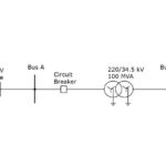
Hindalco Industries Limited, a flagship enterprise of the Aditya Birla Group, operates a vertically integrated aluminium production facility at Renukoot, which is powered by a Captive Power Plant located at Renusagar, approximately 35 kilometers away. The Renusagar complex comprises ten turbo-generator units of varying capacities, collectively delivering a generation capacity of 829.5 MW. Power is transmitted from Renusagar to Renukoot through a dedicated 132 kV transmission network consisting of ten transmission lines, including four multi-circuit lines mounted on shared tower infrastructure. Renukoot System is connected to the RIhand Hydel 132 kV Grid network.
System Configuration and Challenges
- Transmission Voltage: 132 kV
- Line Length: ~35 km
- Topology: Hilly terrain with frequent lightning activity
- Communication Infrastructure: Single-mode Optical Ground Wire (OPGW)
- Protection Architecture: Distance and current differential protection with Power Line Carrier Communication (PLCC) at both ends
The geographical and meteorological conditions contribute significantly to fault incidence, particularly lightning-induced phase-to-ground faults, which frequently result in fault currents ranging between 20–25 kA. These are predominantly fed by the turbogenerators, exacerbating mechanical and thermal stress on generator-transformer units.
As the complete power system operates at 132 kV level that is prone to various faults like lightning strikes and subsequent back flashovers due to transmission lines passing through hilly terrain and a weak grid, which often does not support during power disturbances. This situation creates a power system that needs to be well protected at all times and have faster clearing of faults in order to prevent cascading tripping of Units and subsequent black out causing huge monetary losses.
Fault types in transmission lines generally are Phase to Ground Faults caused by Lightning strikes the fault current generally runs into 20-25 kAmps. This high amount of fault current is normally fed by the Turbo Generators at Renusagar.
Protection Limitations and Operational Concerns
During monsoon season, when the lighting strike probability is very high, the fault happens 10-15 times in a month and regularly the largest generator feeds the fault though the generator transformer, which causes severe electrical and mechanical stresses in the winding. To eliminate the extended fault feeding time of the machines ultra high-speed travelling wave fault relay was installed, which has reduced the fault clearing time drastically by 01 cycle – thus significantly reducing the stresses of the machine during fault conditions.
Am added advantage was – the system voltage dip during fault conditions was also significantly reduced, which has extended the life of the auxiliary system majorly consisted of HT and LT motors – and the process gained tremendous benefit due to reduced fluctuations in the power quality.
Conventional current differential protection schemes typically operate within 18–20 milliseconds, followed by circuit breaker operation in 30–35 milliseconds, resulting in an aggregate fault clearing time of approximately 50–55 milliseconds (~3 cycles). This duration allows substantial fault energy to be absorbed by generator and transformer windings, accelerating insulation deterioration and increasing the likelihood of catastrophic equipment failure. Historical incidents at Renusagar include failures of generator transformers and turbo-generator sets attributed to such sustained fault conditions.
Rationale for UHS Travelling Wave Protection
To curtail the exposure of generation assets to high fault currents and mitigate cascading failures, an advanced Ultra-High-Speed Travelling Wave Protection scheme was commissioned on one of the most fault-prone multi-circuit lines.
Operating Principle
Travelling wave relays utilise high-frequency transients generated during fault inception. These transients, or travelling waves, propagate along the transmission line and are captured at both terminals using high-bandwidth sensors. By precisely analysing the arrival time of these wavefronts, the relay system can:
- Detect and classify faults with sub-cycle latency
- Accurately localise the fault with sub-kilometer precision
- Initiate tripping commands within 3–5 milliseconds
Strategic Advantages
- Drastic reduction in fault clearing time (by nearly one full cycle)
- Minimisation of mechanical and thermal stress on generator windings
- Mitigation of voltage sags, enhancing power quality
- Protection of critical auxiliary systems (e.g., HT/LT motors)
- Improved overall system resilience and reliability
Implementation Overview
Selection Criteria
A high-risk transmission line, known for recurrent lightning-induced faults and hosting multiple circuits on a shared tower structure, was selected as the pilot implementation site. Its challenging topography and historical data made it a suitable candidate for demonstrating the efficacy of travelling wave-based protection.
System Integration
- Relay Type: Ultra High Sped Travelling Wave Protection Relay and Fault locator
- Data Acquisition: High-speed voltage and current sensors with synchronised sampling
- Communication: High-fidelity optical fibre link using OPGW for real-time relay coordination
- Fault Location Algorithm: Time-domain reflectometry based on wave arrival times
Fault Incident Summary
A phase-to-ground fault event was recorded during the monsoon season on the selected 132 kV line. The UHS relay responded with exceptional speed, far outperforming conventional schemes.
Performance Metrics
- Relay Detection Time: ~1–2 milliseconds
- Breaker Tripping Time: ~30–35 milliseconds
- Total Clearing Time: ~35–40 milliseconds
(~2 cycles) - Fault Localization Accuracy: Within ±100 meters of the actual fault location
Observations
- Substantial reduction in system stress during the fault, as evidenced by post-event thermal assessments
- Diminished voltage dips, preserving the operation of sensitive HT and LT motors
- No auxiliary system interruptions during the fault event
- Significant improvement in post-fault voltage recovery time
This article presents the technical aspects of the Ultra High-Speed Travelling Fault Relay applications at one of the Transmission Lines at Renusagar and the detailed analysis of the recent fault delving deeper in to the amalgamation of theory and practical data.
UHS Protection and Travelling-Wave Fault Locator
Recent developments in the design of protective relays have brought about protection elements that can operate on traveling waves and incremental quantities. One such Ultra-High-Speed (UHS) protective relay operates at speeds as fast as 1 mS using traveling-wave and incremental quantity methods.
This article discusses a UHS relay that includes: a traveling-wave differential scheme (TW87), a permissive overreaching transfer tripping (POTT) scheme that uses traveling-wave directional (TW32) and incremental quantity-based time-domain directional (TD32) elements, and an underreaching incremental quantity-based time-domain distance element (TD21).
In addition to UHS protective functions, the relay performs accurate fault locating using Double-Ended Traveling-Wave Fault Locating (DETWFL) and Communications-Independent Single-Ended Traveling-Wave Fault Locating (SETWFL).
While this article does not aim to derive all the theory of each protection function in the UHS relay, it does provide a working knowledge of the traveling-wave elements and the incremental quantity elements.
Traveling Waves
When a fault or disturbance occurs, the step change in voltage causes both a current and a voltage Traveling Wave (TW) to be launched in both directions from the point of origin.
TW Differential Scheme (TW87) and TW Directional Scheme (TW32)
The UHS protective relay incorporates a traveling wave (TW)-based directional (TW32) element and a TW-based differential (TW87) scheme.
For the TW87 scheme, the Current Transformer (CT) polarities should face outward from the differential zone, similar to those in a phasor-based line current differential (87L) setup. This configuration ensures that the currents from the two relays add up to zero when through current is present, maintaining the same relationship for TWs.
In the event of an internal line fault, the initial current TWs detected at both the local and remote end terminals will have the same polarity and will be separated by less than the traveling-wave line propagation time (TWLPT). TWLPT, the one-way end-to-end TW travel time of the transmission line, is a critical configuration setting for UHS relays. Accurate TWLPT settings are essential for the security of the TW87 protection scheme and the precision of TW Fault Location (TWFL) methods. TWLPT is determined using transient records captured during line energisation tests.
For external line faults, the initial current TWs detected at the local and remote line terminals will have opposite polarities and will be separated by exactly the TWLPT. This principle underpins the TW87 scheme. The TW87 scheme requires UHS relays at each line terminal to exchange local voltage and current signal measurements sampled at 1 MHz via a dedicated fiber-optic channel. With this channel, the relays synchronise data over the channel without relying on an external time source.
The polarities of the first voltage and current TWs arriving at a terminal after a fault indicate the fault direction. For forward faults, the voltage TW and current TW have opposite polarities; for reverse faults, they have the same polarity. This principle forms the basis of the TW32 element, which is used for fast keying of the permissive overreach transfer trip (POTT) scheme and is not intended for direct circuit breaker tripping.
Incremental Quantity Directional Element (TD32) and Distance Elements (TD21)
The UHS protective relays included protection elements that use voltage and current incremental quantities, which are the differences between a present instantaneous sample and a one cycle-old sample. The incremental quantities contain the pure fault voltage and current information and exclude any pre-fault load information. These signals are filtered with a low-pass filter and then applied to directional and distance elements. The relay calculates incremental voltage and incremental replica currents for six measurement loops.
The TD21 element is a fast-underreaching Zone 1 distance element used for instantaneous tripping. This element calculates the incremental voltage change at the reach point and compares it with the pre-fault voltage at the same reach point. For an in-zone fault within the reach point, the calculated incremental voltage change at the reach point will be greater than the pre-fault reach point voltage.
For a fault beyond the reach point (outside the zone of protection), the calculated incremental voltage change at the reach point will be less than the pre-fault reach point voltage.
The TD32 element provides a fast, secure, and dependable directional indication. This element is used as part of a POTT scheme and is not intended for direct tripping of circuit breakers. The TD32 element calculates the operating torque as a product of sign-inverted incremental loop voltage and incremental replica loop current. It also calculates the forward and reverse restraining torques based on the incremental replica loop current and relay settings for the forward/reverse impedance thresholds.
For a forward fault, the incremental loop voltage and incremental replica loop current have opposite polarities, which results in a positive torque, and then TD32F declares forward direction. For a reverse fault, the incremental loop voltage and incremental replica loop current have the same polarity, which results in a negative torque, and then TD32R declares reverse direction. The calculated torques are integrated and the operating torque is compared with the restraining torques.
TD32F if Dv • – DiZ > TD32ZF• Di Z2
TD32R if Dv • – DiZ < TD32ZR • Di Z2
Dv is the incremental voltage change
DiZ is the loop incremental replica current change
Travelling Wave Fault Location (TWFL)
Faults on transmission lines generate TWs that propagate from the location of the fault to the line terminals. The fault location can be calculated based on the TW arrival times, the Line Length (LL), and the TWLPT. TWFL is widely popular with transmission system operators, largely due to its field proven track record with reported errors being within one tower span (300 m or 1,000 ft) on average, regardless of LL. The accuracy of impedance-based fault-locating methods is approximately 0.5 to 2% of LL for the double-ended method and 2 to 5% of LL for the single-ended method. For a 100 km transmission line, a ±1% error requires inspection of the likely 2 km section (about seven towers). The UHS relays applied in this pilot application include the following methods:
- Single-Ended Traveling-Wave-Based Fault Locating (SETWFL)
- Double-Ended Traveling-Wave-Based Fault Locating (DETWFL)
- Single-Ended Impedance-Based Fault-Locating (SEZFL)
- Double-Ended Impedance-Based Fault Locating (DEZFL)
To be continued…

Raman Bajpai holds a Bachelor’s degree in Electrical & Electronics Engineering and an MBA in Marketing Management. He is currently serving as General Manager (Electrical & Instrumentation) at Hindalco Industries Limited, Hirakud (Power & Smelter). He has over two decades of experience in the areas of Protection, Control & Automation Systems, Transformers, Motors, and Instrumentation. His core competencies lie in digitalization, innovation in electrical systems, and enhancing power system reliability and stability. Bajpai has played a key role in stabilizing complex industrial power systems, contributing to improved operational reliability and safety performance. He joined Hindalco in 2008 at the Renusagar Power Division and has previously held technical and leadership roles at Siemens, HEG, and the Jaypee Group.


