In order to arrest global warming, more than 110 countries have taken up the most urgent mission to achieve net zero carbon emission by 2050. Renewable energy will continue to rise in the upcoming years phasing out fossil fuels and, reduce greenhouse gas emissions. In the present scenario, solar and wind energy are in the forefront of transformations taking place across the global energy system.
But they have many constraints like availability of sunlight, they require lot of land space, unpredictable power generation, high cost to invest etc. Ocean energy is predictable, offering a stable energy supply and is emerging as an alternative to conventional fossil fuel resources.
It has a very high-power density of about 2 to 3 kW/m2 compared to wind with 0.4 to 0.6 kW/m2 and solar with 0.1 to 0.2 kW/m2 energy densities. This means wave power density is 100 times more than that of solar and 10 times higher than that of wind power. Over 40% of the world’s energy needs may be met by wave energy assuming that about one third of the potential wave power can be tapped and conversion efficiency of wave power taken as 40%. It is the only energy source using power from sun that has not yet been commercialised.
Wave energy potential in India is between 40 and 60 GW. The sea has very harsh and corrosive environment, so it is necessary to design the equipment and structures robust enough to face the harshness. But that costs money, and at present LCOE of wave energy is much higher than the cost of other matured renewable energies.
However, in the near future wave energy cost would be reduced considerably due to continuous research work and inventing new technologies. As per National Renewable Energy Laboratory, USA, average LCOE of wave energy in 2020 was about $0.57/kWh and could reach $0.30/kWh by 2033. Further under optimistic scenarios LCOE for WEC could further be reduced to about $0.04 to $0.1 /kWh in the year 2050, compared to $0.049/kWh for solar PV and $0.081/kWh for offshore wind power.
Wave mechanics
As the sun’s thermal radiation changes the air temperatures it generates wind. Wind blowing across the water’s surface creates little disturbances called capillary waves or, ripples that start from gentle breeze. Capillary waves have a rounded crest with a V-shaped trough and, wavelengths less than 1.7 cm. These small ripples give the wind something to ‘grip’ onto to generate larger waves when the wind energy increases and, when the wavelength increases to 1.7cm and above then, capillary wave is transformed to wind wave.
Due to surface tension the capillary waves try to go back to its calm equilibrium condition, but for larger waves generated by strong wind – the restoring force is gravitation. Size, length and speed of the resulting waves mainly depend on three factors namely, wind speed, how long the wind blows continuously over the water, and ‘fetch’ which is the distance over which the wind blows across the water in the same direction. Increasing any of these parameters would increase the size, speed and energy of wind waves up to 30 metres high peak to trough.
When the wind blows over water surface it transfers its energy causing the water to move in circular orbits, rising and falling but generally returning to their original position. The rise and fall of water molecules creates a wave that moves in the direction of the wind. The waves transport energy, not water molecules.
In deep sea, the available wave power resource can be calculated using the following expression:
P = (rg2/64π) . Hs2. Te , where
P = wave power contained within a unit of wavefront length in Wm-1, r = sea water density, g = 9.81 ms-2, which is the gravitational acceleration, Hs2 is the significant wave height, defined as the mean wave height of the third highest waves, Te is the wave energy period and, is taken as 0.86 to 0.91 times the peak wave period of standard spectrum.
Wave energy resources
Wave energy depends on the geographical location, depth of ocean and time. It is estimated that the global energy potential in deep waters ranges from 1 to 10 TW. When waves travel from deep sea to shallow water they lose their energy due to wave breaking and bottom friction. The worldwide distribution of the annual mean wave power in kW/m is shown in FIG – 1.
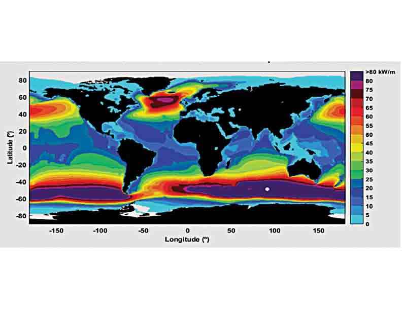
The intergovernmental panel on Climate Change estimates that wave energy could generate up to 29,500 TWh annually which is more than the total global electricity production. International Energy Agency has set a target of installed marine energy capacity of 300 GW by 2050. It is estimated that by using solely 2% of the world’s 800,000 km of coastline, which exceeds a wave power density of 30kW/m, it is possible to generate about 500 GW of electrical energy with 40% conversion efficiency.
Given India’s extensive coastline including islands, wave energy is a promising route to generate green electricity. The highest average significant wave height of 3.3 m and wave power of about 50 kW per m has been recorded in the Arabian Sea, whereas near the shore of the Bay of Bengal the wave power ranges from 0 to 15 kW/m. The average wave power along the western coast of India, Lakshadweep Islands and Little Andaman and Nicobar ranges from 10 to 15 kW /m. Also, wave power available along the southerly regions of India near Kanyakumari remains more or less constant round the year with a yearly mean values ranging from 15 to 20 kW/m suggesting a lucrative installation of wave power generating farms in these locations.
The projected all India peak electricity demand is 277 GW for the year 2026-27. Primary estimates of wave energy potential along Indian coast is around 5-15 MW/m, so the estimated potential comes out to be about 40-60 GW. There are two power plant projects currently in the pipeline i.e., a new wave energy plant of 1MW wave energy plant at Vizhinjam, Kerala – and a 65 kW ocean thermal energy conversion plant in Lakshadweep.
Advantages and disadvantages of wave power
The benefits of this technology
- The biggest advantage of wave energy is that it is a clean and green energy source, which does not require the use of land, a scarce resource of many countries and it has a low environmental impact.
- Wave energy has high power density compared to other renewable resources of energy.
- Wave patterns are more regular and quite predictable than other forms of renewable energy since ocean waves are driven by gravitational pull of the moon – and by winds which follow a regular pattern. Hence, better planning and management to harness this form is possible.
- Wave farms are generally located far away from the shore, thus they do not spoil the aesthetics of the natural beauty of the beach.
- This can be very useful for remote islands enabling these places to generate their own electricity freeing them from vagaries of fuel shipment.
- Once the plant is installed its operating cost is very low.
- Wave energy can lead to electricity price stability because, unlike fossil fuels there is practically no supply variation of the source of energy.
But there are many challenges as mentioned hereafter
- High initial cost of its plant and equipment makes the project not lucrative to the investors. Also, strict maintenance programmes are to be followed to have trouble free operation because, they are ceaselessly exposed to the ocean’s wrath, corrosion due to saltwater and facing fierce storm. The cost of other modes of generation of electricity especially, fossil fuels is far less. Presently, total installation cost including plant and equipment and electrics of a coal fired power plant is $3 million/MW whereas, the same for a bottom standing wave power plant is about $10 million/MW. However, as there is continuous technology updating, installation costs would likely to be reduced further in future.
- Height, frequency and, wave direction of waves changes depending on season and weather condition resulting in variation in energy output. In order to bolster the reliability of wave energy it is necessary to integrate the system with the other grids and storage system that would ensure uninterrupted power supply.
- Only select locations that are graced with strong and consistent waves are suitable for harvesting wave energy with good efficiency.
- Grid integration and energy transmission using long underground power and control cables to on-shore grids and synchronisation of both the systems presents its own labyrinth of complexities and necessitates meticulous planning.
Classification of wave energy converters
- Shoreline devices that are installed on the coast at hot-spots governed by shoreline geology, tidal range, conservation of shoreline beauty etc.
- Near shore devices that are installed in water depths up to 20m from the shoreline, within I km of the shore and power generated is transmitted to the grid on the shore through electrical cables. Examples are Wave Star, Wave Dragon, Oyster, Archimedes Wave swing etc.
- Off shore devices are installed in deep water at a depth of more than 40m in the deep sea and are subjected to powerful wave regimes and strong winds. Examples are Point absorbers, Attenuator which is a floating object with multiple arms with hinged joints. As the wave passes them the hinged arms bend as per the contour of the waves and generate energy. Amongst numerous wave energy converter devices, the Point Absorber Wave Energy Converter (PAWEC) concept is one of the simplest, cost effective, most-broad based and most promising concept.
Point Absorber Energy (PAE) harvester
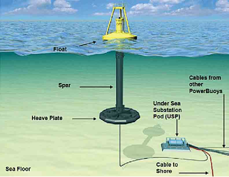
The point absorber is a floating structure, which absorbs the energy of the incident wave coming from every direction. These devices are small relative to the wave length, that enable them immune to the direction of the waves and does not affect the effectiveness of the device. They are able to convert energy from a wave front larger than the dimensions of the PAE harvester. Typical arrangement of a PAE harvester is shown in FIG – 2. There are several companies manufacturing PAE converters, and the key players are Ocean Power Technologies (OPT) who developed PowerBuoy and, CorPower Ocean.
PowerBuoy, model PB150, nominal capacity 150kW
Typical arrangement of the device is shown in FIG – 2, which consists of two principal parts: A spar floating in a relatively stationary position due to a mooring system – and a heave plate that reduces the heave motion. The wave motion oscillates the buoy floating on the sea up and down around the spar. The oscillations of the float at the top drive the generator contained in the spar that converts mechanical motion into electrical energy.
The captured wave motion can be suitably converted to rotating motion through a system of gears and power a rotating generator. About 42% of WEC use this route. Alternatively, direct drive conversion by deploying a Linear Permanent Generator (LMPG) can be used (30%).
The electrical energy is then sent to the shore by underwater cables. This type of device has several advantages like its ability to operate in a variety of weather conditions, capable of handling waves having heights up to 8 m. If there is a storm that can generate larger waves, PowerBuoy automatically stops the power generation in order to protect the mechanical system. When weather conditions return to normalcy the system starts working again. It has low surface profile, a small horizontal footprint and is suitable for creating a wave farm. Wave propagating through an array of PowerBuoys is minimally affected by each buoy, thereby maximising its efficiency of conversion. Further due to its low surface profile aesthetic impact of a wave farm is less, as it is not prominent when seen from the beach.
Design concept of Linear Permanent Magnet Generator (LPMG)
The LPMGs are used in a direct drive WEC system. It consists of mainly two components namely the floater that functions as wave’s mechanical energy capturer and the power converter converts mechanical energy into electrical energy. Both parts are interconnected. The typical arrangement of a tubular generator is shown in FIG – 3.
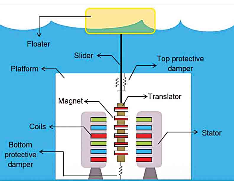
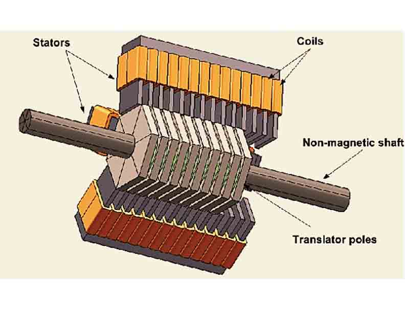
A tubular LPMG with longer translator is formed like a hollow cylindrical body. It has a uniform air gap, thus, it results in a smaller cogging force, no transverse edge effect, and lower manufacturing cost. It is used generally for low power applications. For the high-power applications, flat synchronous generators, as shown in FIG – 4, are mostly used. The magnets are generally made of Neodymium-Iron-Boron, Class N40 material.
The PowerBuoy device developed by Ocean Power Technologies (OPT) is a two-body floating PA as shown in FIG – 2. An additional submerged oscillating body like a spar is added under the buoy – that increases the total mass of the system, thus reduces the natural oscillation of the system. This will enable the WEC to match most common incident waves that have very low frequencies, about 0.1Hz-0.2 Hz. Hundred-year storms and extreme wave conditions were used to design the structures of its model PB150. Hence, it survived Hurricane Irene in 2011.
PowerBuoys are designed strong enough to have (generally) maintenance every three years. Typical dimensions of a PowerBuoy: overall length – 30 m, spar diameter – 1.0 m, float diameter – 2.7 m, Draft – 9.3 m, mooring depth – 25 m to 1000 m, weight – 33,000 kg, power rating – 150 kW.
Test result shows that power generated by a typical PowerBuoy depends on wave height. At wave height less than 2 m it can generate 45 kW, but the same device can generate 150 kW when the wave height is between 2 m to 6 m, and during storm a peak at 400 kW. On an average a commercial PowerBuoy can have nominal power capacity of 150 kW whereas, a single wind turbine can have output of 3 MW. So, a farm of about 20 PowerBuoys is needed to match the output of a single wind turbine. With the small footprint of these buoys, it is easy to install extended wave farm with more than 30 buoys.
Another type of PTO is quite common, which converts up and down movements of the buoy to rotary motion through a direct mechanical drive. FIG – 5 shows the schematic arrangement of such device that consists of mainly a hemispherical floating buoy, a power take off system comprising a rack and pinion mechanism, a Bidirectional Gear (BG) box coupled with a flywheel – and an electric generator – and a Control Stiffness Mechanism (CSM). CSM has four hydraulic cylinders inside the hemisphere connected with a hydraulic accumulator via pipeline inside the main shaft connected to a pressure control unit.
As shown in FIG – 5, the main shaft (3) is coupled to the Bidirectional Gearbox (BG) by the rack and pinion mechanism. The upward and downward motion of the floating buoy is converted into one-way rotation of the output shaft with the help of two numbers of one way bearing provided inside the BG. A one way bearing, also known as a clutch bearing or overrunning clutch, is a mechanical component that allows rotation in one direction only and freewheels in the opposite direction. There are two pinions operated by the rack that moves up and down due to wave motion.
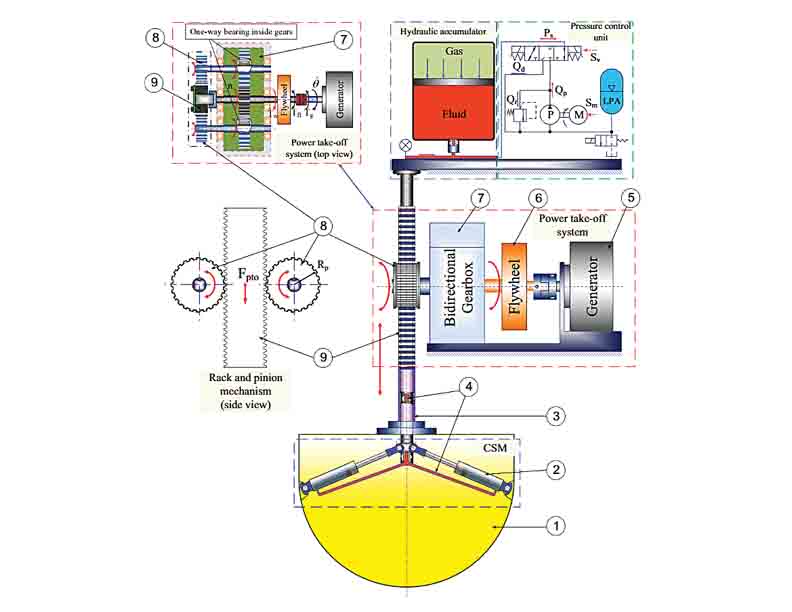
FIG – 5: Schematics of rotary type power take off unit…
The two pinions are fixed to two input shafts and the input shafts are coupled to two driving gears. These two driving gears are engaged with a driven gear to convert bidirectional motion into one-way rotary motion with the help of one way bearings. The output shaft of the BG is connected to the flywheel which is used to store and release rotational energy in order to maintain a constant rotational speed. The output shaft of the flywheel is coupled to an electric generator to generate electric power.
Stiffness Control Mechanism (CSM)
PowerBuoys are essentially vibrating systems, which move up and down with the waves. The natural frequency of the buoy determines the frequency at which it will oscillate most readily. When the frequency of the incoming waves matches the buoy’s natural frequency, the buoy resonates with the incoming waves, leading to maximum amplitude of motion and maximum energy absorption. To optimise power capture under various sea conditions, the buoy’s stiffness need to be adjusted. This is done by incorporating a control system that modifies the effective stiffness of the assembly of the buoy. This control system typically uses a continuously variable hydraulic system to vary the stiffness of the buoy’s system. This control enables the buoy to dynamically adapt to changing wave frequencies and stay tuned to resonance so that it can capture wave energy most efficiently.
The CSM comprises of the following components i.e., a set of four hydraulic cylinders, item 2 inside the buoy and a pressure control unit as shown in FIG – 5. In order to provide a balance force in vertical direction these 4 cylinders are placed at right angles to each other. When the buoy moves in vertical direction, the fluid pressure inside the 4 cylinders provides a vertical spring force which counteracts the hydrostatic heave force enabling to decrease the equivalent stiffness of WEC. As a result, the natural frequency of the system can be easily tuned to the wave frequencies.
Due to resonance condition width capture ratio is also increased. The pressure control unit as shown in FIG – 5 comprises an electrically operated hydraulic pump M-P that operates along with a control valve SV to pump high pressure fluid QP into the 4 operating hydraulic cylinders. A high pressure hydraulic accumulator maintains the operating pressure PS in the system. There is a safety valve that opens if the operating pressure exceeds the upper safe limit. There is a Low Pressure Accumulator (LPA) for energy saving purpose.
CorPower Ocean AB
CorPower Ocean AB is a Swedish wave energy company based in Stockholm who manufacture and install wave energy point absorber devices. It is a rotationally symmetrical point absorber looking like a buoy with a circular plan view. It is a two body point absorber having similar arrangement as shown in FIG – 2. Its C4 device has been deployed in Portugal in September 2023, 4 km offshore. The device is connected to the Portuguese electricity grid by subsea cable. The 300 kW, C4WEC is 9 m in diameter, 19 m tall and weighs about 60 tonnes. During seven-week on site testing, it exported power up to 600 kW.
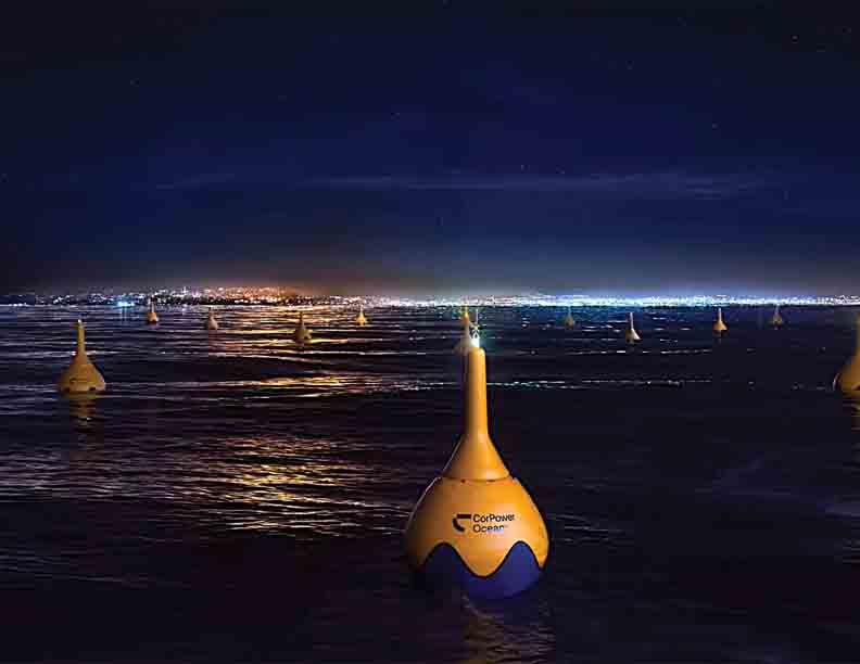
The converter survived a severe storm in 1923, when 19 m tall waves were formed. CorPower has made a plan to install arrays of about 25 such devices as shown in FIG – 6 having a total power output of about 10 MW, with standard 33/66kV electrical connection, comparable to modern offshore wind turbine. The shell of the WEC is fabricated from filament-wound glass reinforced plastic with Divinycell H structural core. This material is ideal for marine application. It provides excellent mechanical properties to a low weight, good chemical resistance, low water absorption, excellent fatigue resistance. It is thermoformable, easy to machine and can be easily repaired with most common glues. A mobile system can be used to construct the hull at site, thus, avoiding cumbersome transportation of a big buoy.
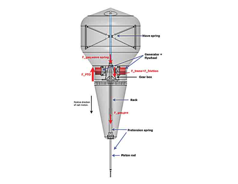
A CorPower WEC broadly consists of the following units (Refer scheme – 7)
Point absorber
It features a buoy with a spar that moves up and down with the waves and is capable of capturing energy from all directions. The composite buoy dancing with the waves drives a drive train located inside the buoy and converts linear to and fro motion into a rotary motion through a system of rack and pinion coupled with a cascade gear train needed to drive a generator to produce electricity. It uses pre-tension system that provides downward force on the buoy using a pneumatic cylinder. This replaces mass that would otherwise be needed to balance the buoyance at midpoint and thereby reducing cost.
Mooring system
The buoy is connected to the sea bed through a pre-tensioned leg mooring system, which also includes a tide regulator to maintain stability. It uses a pneumatic pre-tensioning system to reduce the mass of the oscillating buoy, thus increasing its natural frequency. The pretension system brings down the mass by 40% compared to a conventional gravity balanced WEC.
This simple technique makes the natural oscillation period of the WEC to a value shorter than all incoming ocean waves. This natural state of the WEC is the detuned mode where the device has little response to incoming waves.
Position keeping of the WEC is achieved through the mooring system developed by UMAC. It consists of a flexible rod, tidal regulation linear actuator and, a crossed H-link universal joint. The fluke anchor has a pointed tip that digs 18 m into the seabed ensuring very strong anchoring. The anchor has a circumference of 3.7 m and weighs 37 tonnes. It can withstand a vertical load of 15 MN, can withstand a hundred million load cycles and, can be retrieved within 1 hr.
Power Take Off (PTO) system
The PTO system converts vertical movement of the buoy to rotary motion to rotate the electric generator for generating electricity. It consists of flywheels connected to the rack and pinion device, which drives a cascade gearbox. The design of cascade gearbox is similar to planetary gearbox, and divides a large load onto a multiple of small gears which enables robust and efficient conversion of linear motion to rotation.
The flywheels act as energy storage and switch between being connected to the rack, and being disengaged from the rack. This switching operation is done by a freewheel that is placed between the flywheel and the cascade gearbox. When the flywheel is engaged to the rack, the rack and the flywheel moves with the same acceleration as the rack, and the same relative rotational speed. When the rack starts to decelerate the flywheel gets a higher speed than the driveshaft of the gearbox and, disconnects.
The flywheel stores rotational energy and helps maintain a consistent speed of the generator. It works by absorbing energy during power strokes of the rack and releasing it during other strokes, effectively balancing the energy output. The faster rotation allows for more energy storage. The efficiency of the generator is dependent on the velocity of the flywheel and torque in the generator.
Wave spring system
The device is provided with wave spring system designed to achieve phase control of the buoy enabling the buoy to optimise its performance in accordance with the characteristics of the waves. The wave spring consists of two negative springs that can reduce the hydrostatic force. It allows the buoy to become tuned or detuned with the wave conditions. This means the device can move more freely in calm conditions to capture more energy and, when there is storm it can be stiffened to withstand the mighty storm waves.
Wave spring phase control provides a negative spring function to the device that allows it to perform in resonance with the incoming waves over a wide bandwidth. It provides optimum phase control without information on incoming waves. The wave spring function is deactivated in storms imparting much reduced loading and higher survivability. In this mode the system becomes highly transparent to waves. In normal sea conditions, the buoy is tuned and set in optimal timing with the incoming waves, amplifying the motion and power capture. For example, a 1-metre wave is amplified to a buoy motion of 3 metres, making it highly efficient in capturing wave energy.
Cost analysis
The cost of a point absorber wave energy converter as shown in FIG – 7, varies significantly based on factors like size, materials, and location. Early stage development and harsh ocean environments contribute to high initial cost. However, costs are expected to decrease as the technology matures. Initial capital expenditure (CAPEX) ranged around Euro 20,000/kW in the early stages of development but, is estimated to cost around Euro 6907/kW at present and, 1730/kW by 2050.
Where installed
Some notable point absorber WECs have been operating since 2011 in Portugal, USA, Ghana, Chile, Sweden, Greece, which have been installed by companies like CorPower, PowerBuoy, Seabased, BOLT Lifesaver.
Conclusion
Point absorber WECs represent a promising avenue for generating green electricity. They are particularly attractive for their ability to harness wave energy from waves of various directions and they are very suitable to work in array formation. AI algorithms can optimise PTO parameters like damping and stiffness of PA-WEC – based on incoming wave condition, maximise energy absorption – and even optimise the buoy’s hull shape for maximum energy capture. Having a high yield, the adaptability to different weather conditions, the easy integration into other systems and increasingly reduction in cost of the device due to ongoing research work make it a very promising technology in the coming years.

Rathindra Nath Biswas graduated in Chemical Engineering from Jadavpur University, Calcutta in 1964. He retired as Chief, Mecon, Durgapur.