

A significant proportion of failures in electrical devices result from the deterioration of insulation. The implementation of routine, straightforward tests, along with prompt maintenance prompted by these tests, can often predict and prevent many of these failures. It is essential not to condemn an insulation system or device prematurely; instead, it should undergo complete isolation, cleaning, or servicing, with measurements adjusted for temperature. Accurate interpretation of capacitance and dissipation factor tests typically requires understanding the construction of the apparatus and the characteristics of the specific insulation types employed. Deviations from the normal capacitance of insulation materials can signal abnormal conditions such as the presence of a moisture layer, short circuits, or open circuits in the capacitance network. Dissipation factor measurements provide insights into various conditions affecting the insulation of a diverse range of electrical apparatus. These conditions include:
- Chemical degradation over time and due to temperature, encompassing instances of acute deterioration triggered by localized overheating.
- Contamination caused by water, carbon deposits, substandard oil, dirt, and other chemical substances.
- Significant leakage through cracks and over surfaces.
- Ionization.
- The interpretation of these measurements typically relies on accumulated experience, the equipment manufacturer’s recommendations, and the observation of differences:
- Discrepancies in measurements on the same unit after successive time intervals.
- Variances in measurements between duplicate units or similar components of one unit, tested under identical conditions around the same time. For example, several identical transformers or an individual winding of a three-phase transformer tested separately.
Differences in measurements at various test voltages on one part of a unit. An increase in the slope (tip-up) of a dissipation factor versus voltage curve at a specific voltage indicates the initiation of ionization at that voltage.
Capacitance and Dissipation Factor Relationship
In an ideal insulation system connected to an alternating voltage source, the capacitance current (Ic) and the voltage exhibit perfect quadrature, with the current leading. However, practical applications introduce a loss current (Ir) that aligns with the voltage, as illustrated in Figure 1.
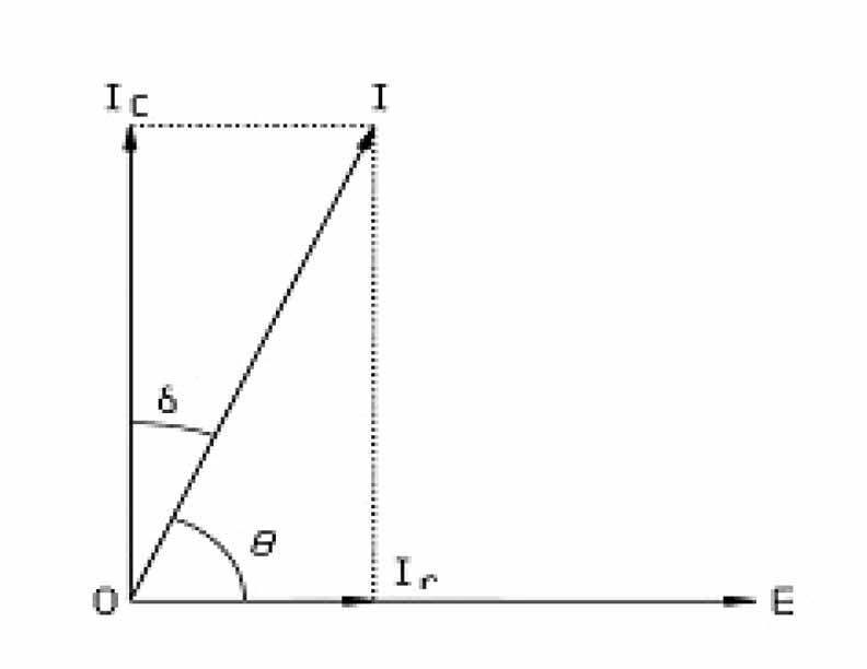
The current drawn by an ideal insulation system, with no losses (Ir = 0), is purely capacitive and leads the voltage by 90° (q = 90°). In reality, no insulation is flawless; there exists a certain level of loss, causing the total current (I) to lead the voltage by a phase angle q (q < 90°). To enhance convenience, the dielectric-loss angle (d) is commonly used, where d = 90° – q. In instances of low power factor insulation, Ic and I are nearly equal in magnitude since the loss component Ir is minimal.
The Power Factor (PF) is defined as:
PF = cos q = sin d = Ir / I
and the Dissipation Factor (DF) is defined as:
DF = cot q = tan d = Ir / Ic
So, PF =DF/√ (1+DF2) and DF =PF/√ (1 – PF2)
When the angle d is extremely small, the sine of d is practically equivalent to the tangent of d. For instance, at power factor values below 10%, the disparity is less than 0.5% of the reading, and for power factor values below 20%, the difference is less than 2% of the reading. The value of Ic will be nearly 99.5% of the value I for power factor (sin d) values up to 10% and approximately 98% for power factor values up to 20%.
Condition Monitoring of Power Transfomers by Capacitance and Tan Delta Measurement
CPRI-Noida performed capacitance and tan delta measurement of various utilities; specially Delhi Transco Ltd., Delhi; for seven years for their EHV sub-station power transformers.
For this work, Doble, USA make Automatic Insulation Analyzer, Model M4100/Controller M4200 (Range: 0-12 kV, Capacitance range: 0 to 5.0 mf and Tan d range (%): 0 to 9.999) used, as shown in the figure 2.

C & Tan Delta measurement of transformer windings
The dissipation factor (tan delta) represents the gross defects and overall dielectric losses in the insulation. In order to assess the state and quality of the entire mass of the transformer insulation, following six test schemes used during the measurement of the C & tan delta:
CH: HV winding to tank.
CH + CHL: HV winding versus LV winding grounded to tank.
CHL: HV winding versus LV winding (ungrounded).
CL: LV winding versus HV winding grounded to tank.
CL+ CHL: LV winding versus HV winding grounded to tank.
Test Procedure: First of all, the transformer is fully isolated from the system. After that, all HV side phase terminals along with neutral terminal are shorted together. In the same way, all LV phase terminals are shorted together along with neutral.
If tertiary winding is also provided, it is better to short their terminals together. The winding connections are shown in figure 3 and figure 4.


The standard test connections for two-winding transformers are outlined in Figure 5 and Figure 6. The test procedure and settings used for different capacitance measurement are given in table 1. The high voltage cable is placed on the winding in the Energize column, and the low voltage lead is placed on the opposite winding.

Analysis of Test Results: Modern oil-filled power transformers are expected to exhibit insulation power factors of 0.7% or lower at 20°C. In contrast, older power transformers, oil-filled distribution transformers, and various liquid-filled or dry-type power and distribution transformers might have power factors exceeding 0.7%.
Comparisons of the capacitance (charging current) of CH, CL, and CHL should be made against factory data, previous test results (if available), or test results from similar units. Capacitance, influenced by winding geometry, is anticipated to remain stable with temperature and age. Any changes in capacitance suggest winding movement, possibly due to a through fault, with CL and CHL insulations being susceptible to such alterations.
An elevated dissipation factor beyond typical values may signal conditions mentioned earlier, whether general or localized. A rise in dissipation factor, particularly when accompanied by a potential increase in capacitance, often points to excessive moisture in the insulation. An increase in dissipation factor alone could result from thermal deterioration or contamination other than water.
For accurate measurements, it’s crucial that bushing and pothead surfaces, terminal boards, etc., are clean and dry. Any leakage over terminal surfaces might contribute to insulation losses, potentially yielding a false assessment of its condition, if excessive.

C & Tan Delta measurement of transformer bushings
The primary function of a bushing is to provide an insulated entrance for an energized conductor into an apparatus tank or chamber. A bushing may also serve as a support for other energized parts of the apparatus.
Condenser Type:
- Oil-Impregnated Paper Insulation, with Interspersed Conducting (Condenser) Layers or Oil-Impregnated Paper Insulation, Continuously Wound with Interleaved Lined Paper Layers.
- Resin-Bonded Paper Insulation, with Interspersed Conducting (Condenser) Layers.
Non-condenser Type:
- Solid Core, or Alternate Layers of Solid and Liquid Insulation.
- Solid Mass of Homogeneous Insulating Material (e.g., Solid Porcelain).
- Gas Filled.
For outdoor bushings, the primary insulation is contained in a weatherproof housing, usually porcelain. The space between the primary insulation and the weathershed is generally filled with an insulating oil or compound (also used are plastic and foam). Some of the solid homogeneous types may use oil to fill the space between the conductor and the inner wall of the weathershed.
Test Procedure: HV terminal of Bushings are connected to HV terminal of the bridge and
the test tap or tan delta point of bushing, as shown
in Figure 7, is connected to the LV terminal of the bridge and the measurements are carried out at ambient temperature and at test voltage 10.0 kV in UST mode of instrument. Overall capacitance measurement schematic of bushing is shown in Figure 8.
Bushings of this design are tested by the Overall test method (GST) if they are isolated from other parts of apparatus in which they may be mounted (generally not practical), or by the UST method. The latter is a test on C1, the conductor to tap insulation.
The power factor and capacitance recorded are compared with one or more of the following:
- Nameplate data.
- Results of prior tests on the same bushing.
- Results of similar tests on similar bushings.
Analysis of Test Results: Typically, power factors for contemporary condenser bushings, when corrected to 20°C, hover around 0.7%. Capacitances should fall within a range of 5 to 10% of the nameplate value, contingent on the total number of condenser layers. An uptick in power factors suggests potential contamination or insulation deterioration. Increased capacitance raises concerns about the likelihood of short-circuited condenser layers. Conversely, decreased capacitance may indicate the potential presence of a floating ground sleeve, or an open or poorly connected test tap.
Occasionally, negative power factors, accompanied by minor decreases in capacitance or charging current, are observed. These occurrences may stem from unusual external surface leakage conditions or internal leakages caused by carbon tracks.
Case Study
Here is a case study that has been discussed along with data measured at site, which mostly reflects the causes of high tan delta values received.
The case study involves a 100 MVA, 220/66-33/11 kV, 3- winding Transformer. Tan delta testing for this transformer was conducted on 10.11.2012, 21.12.2013, and 22.12.2013. Initially, on 10.11.2012, the insulation condition of the transformer was deemed satisfactory. However, during the condition monitoring scheduled on 21.12.2013, one year later, an alarming increase in tan delta values was observed for LV-Earth and 66 kV Y-Phase bushing. Additionally, the bushing capacitance had nearly doubled.
This raised suspicions of a potential issue with the bushing rather than the LV winding. Consequently, the Y-Phase bushing was replaced with a new one. This replacement led to an improvement in the LV-E tan delta, restoring it to its previous value. As a result, it was deduced that the deteriorated bushing was adversely impacting the tan delta value of the winding. The measurement values are provided in Table 2.

Conclusions
Based on the findings from the case, it becomes apparent that C & Tan delta measurements are highly effective tools for assessing the condition of power transformers in the field. As the voltages in the electric grid increase, the presence of conducted and radiated noise in measurement environments poses a challenge to obtaining stable readings. However, capacitance and power factor measurements in paper-oil insulation systems remain unaffected by applied voltage within the 28V and 10kV range.
The introduction of alternative noise-reduction techniques and advancements in high-power electronics shows promise for enhancing packaging improvements. The ongoing integration of these technologies, coupled with evolving test methods alongside C & Tan delta measurements, is anticipated to result in accurate measurements, robust health monitoring, improved safety measures, swift recovery from issues, and efficient utilization of both human and capital resources.

Lakshmi Narain Giri completed his Post Graduation in Electrical Engineering from Madan Mohan Malviya Engineering College Gorakhpur (U.P.). Currently he is working as an Engineering-Officer in CPRI, RTL, Noida and having eighteen years’ experience in the field of high voltage testing, EHV Substation Equipment Condition Monitoring and Third Party Inspection of Power Transformers.

Gangeshwar Singh completed his graduation in Electrical Engineering from JSS Academy of Technical Education, Noida, Uttar Pradesh. Currently he is working as an Engineering-Officer in the High Voltage Testing Laboratory at CPRI, RTL, Noida and have four years of experience in the field of testing and certification in High Voltage and Ultra High Voltage equipment.

Satish Kumar completed his graduation in Engineering from Janardan Rai Nagar Rajasthan Vidyapeeth University in Udaipur, Rajasthan. Currently he is working as Engineering-Officer in High Voltage Testing Laboratory a CPRI, RTL, Noida and have Thirty years of experience in the field of testing and certification in high voltage.

Manoj Kumar Jaiswal completed his Post Graduation in Electrical Engineering from Indian Institute of Technology (IIT), Roorkee. Currently, he is the Unit Head and Joint Director of CPRI, RTL, Noida and have thirty years of experience in the field of testing, certification and consultancy in High Voltage, Ultra High Voltage, Energy Meters, LED and Cables.


