In the present scenario, vacuum circuit breakers are used up to 33kV and SF6 circuit breakers from 66kV and above voltage class. They will be dealt with in this article. The most important parameters like Arcing Phenomena, Arc Voltage, TOV (Temporary Over Voltages), RRRV (Rate of Raise of Recovery voltage etc.) will also be narrated in this article. I shall at the same time highlight the basic concept on how the main contact is saved from the effect of arcing through arcing contacts.
The circuit breaker is a mechanical switching device in power-systems capable of:
- making, carrying and breaking currents under normal circuit conditions.
- breaking currents under abnormal/faulty conditions.
Applications
Switching and controlling of:
- Transmission overhead lines and power cables
- Transformers and shunt reactors
- Capacitor banks and harmonic filters
- Generator switching
- Motor switching
- Bus tie & transfer switching
Status of usage in present scenario
Usage of vacuum and SF6 gas: After all other interrupting media have been phased-out, now only vacuum is used up to 33kV and above this voltage level SF6 gas is used as interrupting /insulation media.
Vacuum circuit breakers
The dielectric strength of vacuum is considerably higher than other interrupting mediums. Hence, a contact separation of around 1 cm is enough to withstand high voltages. In addition, the rate of dielectric recovery of vacuum is much faster than that of air.
The interrupting technique of vacuum circuit-breakers is different from other types of circuit-breakers. The arc is not extinguished by an interrupting medium but by the metal vapour.
Nowadays, vacuum circuit-breakers are predominant in medium voltage levels. They are considered as maintenance-free circuit-breakers due to their simple and reliable design.
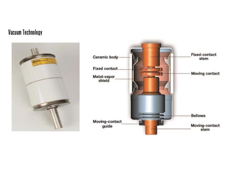
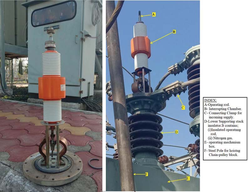
Fig. 1C: 33kV vacuum interrupter assembly shown erected on the lower insulator stack…
Process of repairing under progress
There had been a failure of 33kV vacuum circuit breaker damaging the vacuum interrupter in one of the stations in M.P. Repairing work in progress by replacing the Interrupting chamber assembly with a new one:
- The photograph in the fig.1B is depicting the 33kV vacuum interrupter mounted on the bottom flange of the Interrupter Chamber.
- The photograph in fig.1C depicts 33kV Vacuum interrupter assembly shown erected on the lower insulator stack.
Definition of arc voltage, restriking voltage & RRRV
- Arc voltage: The voltage across the contacts of circuit breaker is the arc voltage when the arc persists. (Refer figure 2)
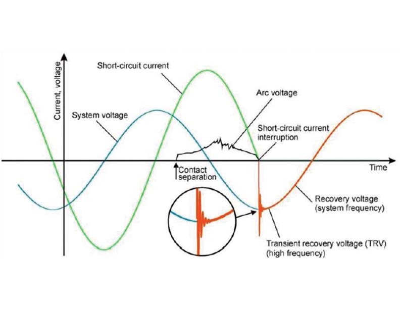
- Restriking Voltage: Interruption will take place at an instant when the alternating current reaches zero and the arc has quenched out. Interruption current reaches zero and the arc has quenched. After the arc extinction, a voltage shall appear that is transient in nature. This transient component of voltage contains multi- frequencies. It is also known as Transient Recovery Voltage (TRV).
- Requirement: After the arc extinction, the insulating medium between the contacts must withstand the rapidly increasing recovery voltage.
- Recovery Voltage: The power frequency RMS voltage, which appears across the breaker contacts at the instant of arc being extinguished and the transient oscillations die-out is called the recovery voltage. (Refer figure 5)
RRRV (Rate of rise of Restriking voltage). (Refer figure 3)
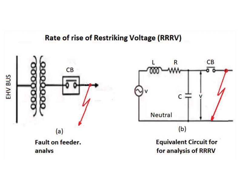
When fault occurs {Refer figure 3(a)}, the circuit breaker opens and capacitance C comes in series with L. {Refer figure 3(b)}
This L-C series combination oscillates at the frequency fn=1/(2π√LC) resulting into development of high voltage across the contacts of the circuit breaker, which appears across the capacitor and hence across the contacts of the circuit breaker.
The RRRV (Rate of Rise of Re-striking voltage) is in kV and time is in microsecond, so RRRV is expressed in kV/µ sec.
- Condition: It is the R.R.R.V, which decides whether the arc will re-strike or not. If R.R.R.V is greater than the rate of rise of dielectric-strength between the contacts, the arc will re-strike. The arc will fail to re-strike if R.R.R.V is less than the rate of increase of dielectric strength between the contacts of the breaker.
- Point to note: This phenomenon is taken care-off in SF6 circuit breakers with:
- SF6 puffer interrupters build up pressure through mechanical compression
- Higher pressures lead to greater voltage withstand capability
- Higher gas flow velocities cool the arc more efficiently
- Efficient gas flow clears the contact region of hot gases, contaminants due to arcing and unstable post-arc conductivity
SF6 gas circuit breakers
Characteristics of SF6 gas:
- Highest dielectric strength of any known gas (e.g., 10 times higher than N2)
- Excellent arc extinguishing medium
- Approximately five times heavier than air
- Thermally stable
- Regeneration characteristics after arcing
- Excellent heat transfer properties
- Superior arc quenching capabilities
- Excellent sound attenuation properties
- Non-corrosive, non-toxic, non-flammable, colourless and odourless
- Currently the most predominant insulating medium for Live and Dead Tank circuit breakers at ratings ≥60 kV
Comparison of Dead Tank & Live Tank SF6 circuit breakers
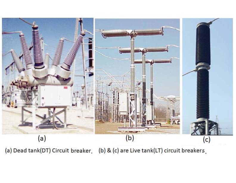
Dead Tank (DT) circuit breaker:
- Grounding of breaker chamber is essential
- Bushing mounted current transformers
- Used in US, Russia and Latin America
Live tank (LT) Circuit breaker:
- Have breaking chamber at line potential
- Current transformers are separately mounted in the substation yard
- Extensively used in UK, Europe, Asia and India
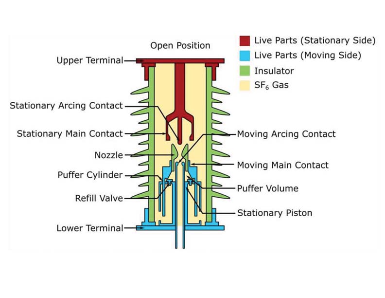
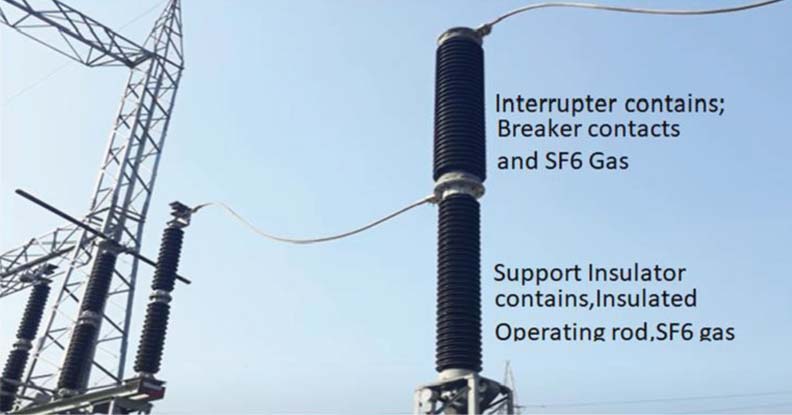
Main components of SF6 circuit breakers
Construction and main components
A complete assembly of a single pressure puffer type SF6 circuit breaker consists of the following parts:
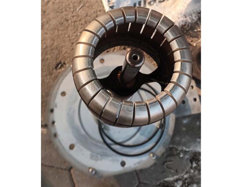
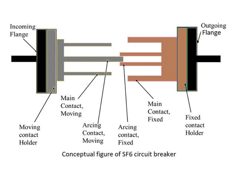
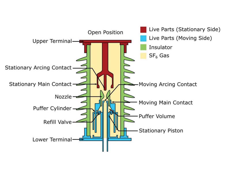
- Interrupter Unit: The separation of circuit breaker contacts, quenching of the resulting arc and interruption of current takes place in the interrupter unit. It houses two sets of contacts, which are commonly called the ‘main’ or ‘normal current carrying contacts’ and ‘arcing contacts.’
Both the types of these contact sets have one stationary contact whilst the other contact is a moving contact. Current carriers (providing connection to the external circuit breaker terminals) are connected to the stationary and moving main contacts. The tips of all circuit breaker contacts are coated with a copper-tungsten arc-resistant material.
The main body of the interrupter (which is filled with SF6 gas) contains a moving puffer cylinder that can axially slide upward and downward along the contacts. There is one stationary piston inside the cylinder that is fixed with other stationary parts of the SF6 circuit breaker, in such a way that it cannot change its position during the movement of the cylinder. A nozzle is located at the opening of the cylinder.
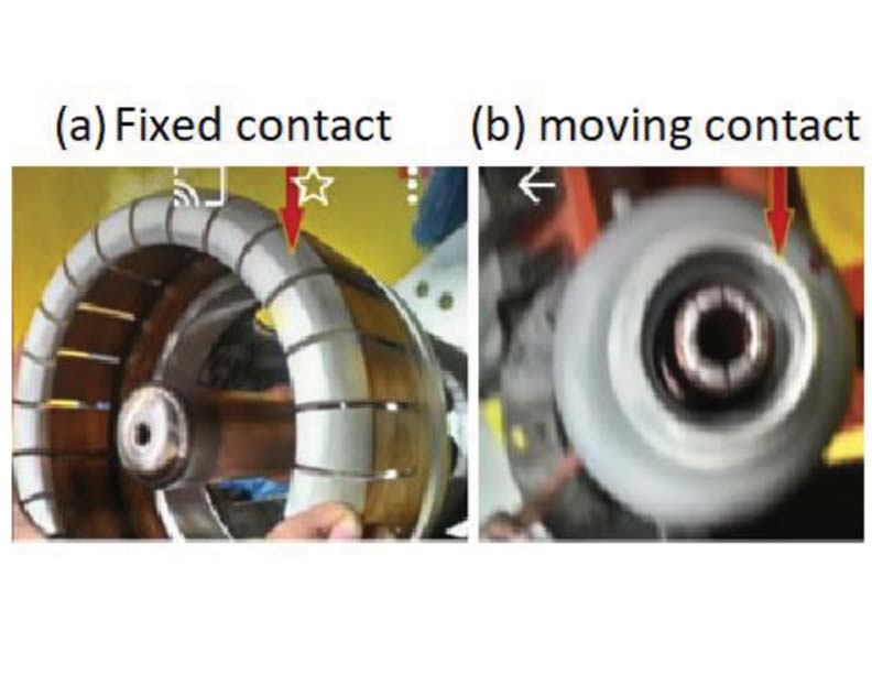
In order to enlighten the reader about how the fixed contact assembly and moving contact assembly look-like, I have posted 2- pictures. {Refer figure 9(a) & (b)}
It may be noticed that:
- Fixed contact assembly: It contains a flexible MAIN CONTACT and a rod like contact placed in the middle of the Flexible contact is the ARCING CONTACT. The length of the Arcing contact is a little longer than the main contact.
- Moving contact assembly: It is mounted in the lower portion of the SF6 gas circuit breaker – and is installed over the lower insulated stack. The arcing contact is found to be little shorter than the main contact.
Interrupting Chamber
The interrupter unit is vertically mounted on top of an insulating stack, which is made up of a hollow insulator encapsulating the drive rod that connects the mechanical operating mechanism of the circuit breaker to the moving contacts housed within the interrupter.
Depending on the voltage rating of the system, the insulating stack may be a single piece, or multiple segments mechanically coupled in series. Just like any other insulator, it provides adequate line-to-ground dry arcing and creepage distance to prevent flashovers associated with transient over voltages and the ambient pollution. The complete circuit breaker unit is usually fixed on a steel structure that is erected on the concrete foundation.
Conceptual figure of SF6 circuit breaker operating chamber (Refer figure 8)
Note
- It can be noticed that arcing contacts are longer than the main contacts
- During closing or opening arc is produced
- Closing operation: Arcing contacts carry the arc and get closed prior to the main-contacts. Thus, arc is quenched and the main contacts are not subjected to hazards of arcing
- Opening operation: Arcing contacts carry the arc and get opened prior to the main contacts. Thus, quenching the arc and the main contacts are not subjected to hazards of arcing.
Working of SF6 circuit breakers
Figure 5 has been reproduced as figure 9 for ready reference indicating the parts of the SF6 circuit breaker in the interrupter chamber:
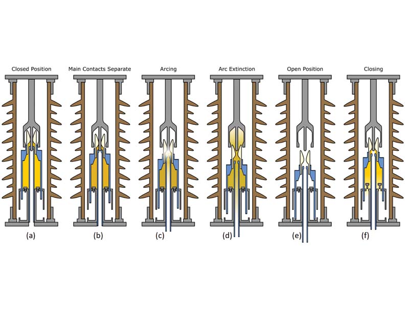
In the normal condition, the circuit breaker contacts are closed and current flows from one contact carrier to the other via the main contacts. (Refer figure 10 (a)}
Circuit breaker opening operation
- When the circuit breaker control panel receives an opening command (to clear a fault or disconnect part of a network), it sends a signal to the trip coil of the mechanical operating mechanism, which in turn releases the latch holding the charged opening spring.
- As the opening spring discharges, it pulls the drive rod (connected to the interrupter) in a linear direction, which causes the moving contacts and puffer cylinder to move downwards. {Refer figure10 (b)}
- The movement of the puffer cylinder against the stationary piston leads to a decrease in the puffer cylinder’s internal volume, which causes compression of the SF6 gas inside the cylinder. Due to contact overlap, gas compression starts before any contacts open.
- As the downward movement continues, the main contacts separate and the current commutates to the arcing contacts which are still in the closed position (due to their physically longer in construction) {Refer figure10(b)}.
- During the course of further opening, the arcing contacts start to separate and an arc is established between them. {Refer figure10(c)}
- As the arc flows, it blocks the flow of SF6 gas through the nozzle to some extent. Thus, the gas pressure in the puffer cylinder continues to increase.
- When the sinusoidal current waveform approaches zero, the arc becomes relatively weak and the pressurised SF6 gas inside the puffer cylinder flows axially (through nozzle) over the arc length.
- This blast of SF6 gas removes the thermal energy in the contact gap and reduces the degree of ionization (electrical conductivity) such that the arc is extinguished. {Refer figure 10 (d)}
- When the arc is interrupted, Transient Recovery Voltage (TRV) starts to appear across the contacts. {Refer figure 10 (e)}
Constraints:
- The opening speed of the circuit breaker contacts should be fast enough to create an adequate contact separation distance to withstand this voltage stress.
- Re-ignition or Re-strike phenomenon: In case the contact gap’s dielectric strength is lower than TRV stress, the arc will be re-established, this phenomenon is commonly called circuit breaker re-ignition or re-strike.
Circuit breaker closing operation
- During the circuit breaker closing sequence, the closing coil releases the energy of the closing spring, which causes the contacts to move towards each other. {Refer figure 10(f)}.
- Ultimately bringing them to their normal closed position. {Refer figure 10(a)}
- At the same time, SF6 gas is redrawn into the puffer cylinder making the circuit breaker ready for the next operation.
Constraint:
- Pre-Strike: Whilst closing, a circuit breaker can sometimes experience an event known as pre-strike.
- As the contacts move towards each other during closing, the contact gap’s dielectric strength decreases.
- At some point, the voltage stress across the contact gap exceeds its dielectric strength, thus producing a ‘pre-strike‘ arc, which bridges the contacts.
Operating duties
It is mandatory to mention operating sequence on the name plate of the circuit breakers. This is required for Auto-reclosure applications on Transmission lines.
The circuit breaker should be able to perform the operating sequence as follows::
The operating duty cycle in accordance with IEC Std. 62271-100 is: O ‑ 0.3 s ‑ CO ‑ 3 min – CO
- Normally the time 3 minutes between the two close-open operations is valid
- The dead time of 0.3 s is based on the recovery time of the air surrounding an external arc in the system (i.e. a short-circuit)
- The time of 3 min is the time needed for the operating mechanism to restore its power after a O ‑ 0.3 s – CO
Circuit breaker timing test
This test is very essential to verify that the breaker operates within the manufacturer’s specified time limits, which is crucial for proper fault isolation and protection of downstream equipment. The test is performed using specialised Digital Time Interval Meters or Breaker Analysers and involves measuring various parameters.
Parameters measured
- Closing Time: The duration from the closing command to when the main contacts are fully closed.
- Opening Time: The duration from the opening (trip) command to when the main contacts are fully open.
- Pole Discrepancy Time (Synchronization Time): The time difference between when the individual poles of the circuit breaker open or close to ensure smooth operation.
- Close-Open Time (C-O): The time it takes for a breaker to close and then immediately open again in a single operation sequence.
Conclusion and recommendation
- It is recommended to go-in for SF6 gas breakers for EHV level Circuit breakers and vacuum
circuit breakers for and up to 33kV level circuit breakers. - For Transformer & Reactor application it is essential to use the CSD (Control Switching Device) in the closing and opening operations through control panels.
- For transmission line applications in-conjunction with auto-reclose facility, please verify, whether they are equipped with single pole reclosing facility
- In view of fool-proof operations, please ensure that the circuit-breakers are equipped with two trip-coils.
- Please verify that the breakers are equipped with pole-discrepancy trip facility.
- The operating mechanism: preferable is mechanical ones that can be readily got petty repairs carried out by the local mechanics in the remote locations of the sub-stations.

Er. K. K. Murty possesses B.E.(Hons) Elec. Engg., FIE, CE (India), Member-CGRE. He is a former Chief Engineer & HOD (Testing & Commun.), M.P. Power Transmission Co. Ltd. Jabalpur. He has served in MPSEB & MPPTCL, Jabalpur for 33 years at different levels from the Assistant Engineer to the Chief Engineer. Besides professional engagements, he has authored a book titled ‘Compendium of Articles on EHV Substations & Protections for Budding and Practicing Engineers of Transmission Utilities.’ Presently he is rendering services as Sr. Visiting /Guest Faculty, for the In-house Training Institutions of the MPPTCL, Jabalpur and the M.P. East Zone, DISCOM, Jabalpur.