The magnetic core of a transformer serves to guide magnetic flux efficiently between the primary and secondary windings. Ideally, the core material should have a linear magnetization characteristic – so that flux changes linearly with magnetizing current.
In reality, ferromagnetic materials like silicon steel exhibit saturation and hysteresis, leading to non-linear magnetic behaviour. This non-linearity introduces several unwanted effects that influence the voltage, current, and efficiency of the transformer.
Nature of Non-Linearity in Magnetic Core
The non-linear characteristic of a transformer core arises due to:
- a) Hysteresis:
- The main goal in transformer is to generate pure sinusoidal voltage so that load can be applied to sinusoidal wave.
- In ideal case input of the transformer is sinusoidal by which flux inside the transformer becomes sinusoidal as a result emf generated becomes sinusoidal which is applied to electric load.
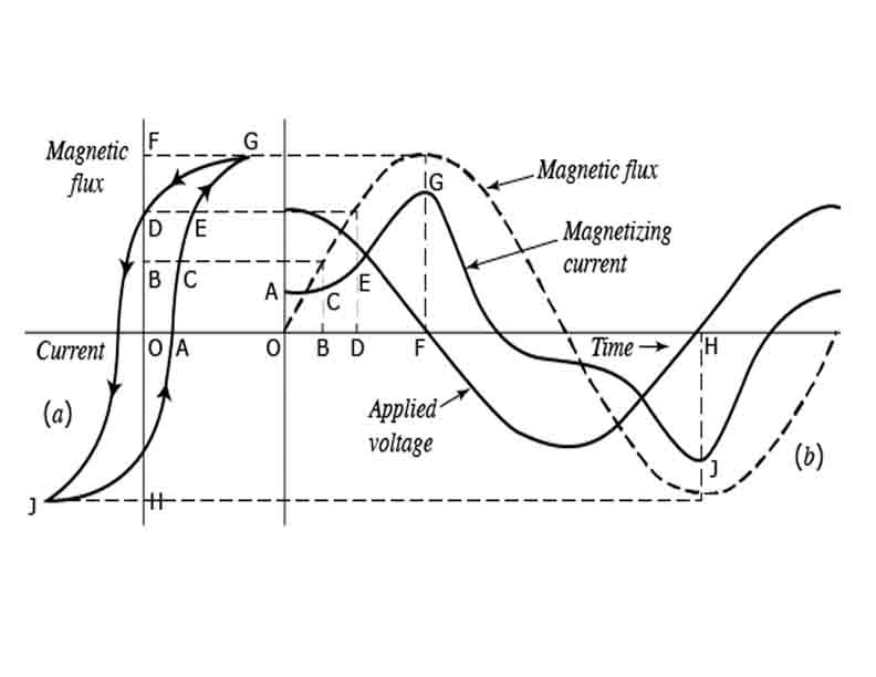
- For the magnetizing current and flux both to be sinusoidal, there initial point or zeros should be the same point.
- Due to hysteresis non linearity, there exist a finite time delay between the magnetizing current and flux. So, the magnetizing current appears peaky wave and flux becomes sinusoidal.
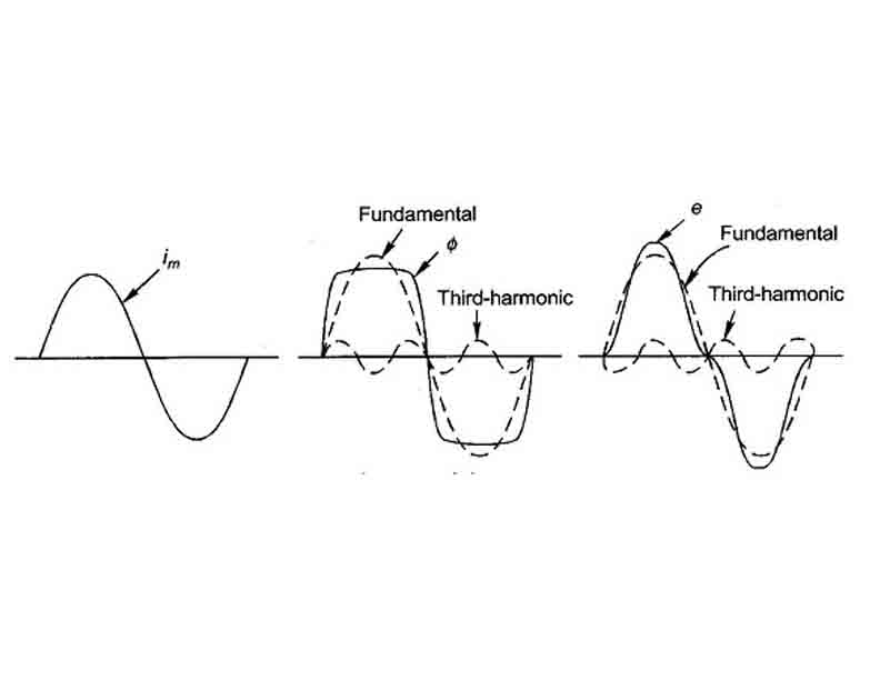
The B-H relationship depends on the previous magnetic state of the material, leading to hysteresis losses. Magnetising current becomes peaky wave because it contains all the odd harmonics with the fundamental. Even harmonics are absent because the peaky magnetising current is symmetrical with respect to real axis. Source does not supply 3rd harmonic current with the magnetising current for it to be peak. So, the question is from where does the 3rd harmonic current come from? Actually, it is generated within transformer itself. But in case, the 3rd harmonic cannot be generated by the transformer then the magnetising current drawn by the transformer will be sinusoidal resulting a flat topped flux wave form that produces peaky emf in primary and secondary which damages the load as shown in the next figure.
b) Magnetic saturation:
- The B–H curve of a ferromagnetic material shows that as the magnetizing force (H) increases, the magnetic flux density (B) initially rises linearly. Beyond a certain point called the knee point or saturation point, further increase in H results in only a small increase in B.
- This region is known as magnetic saturation, where the permeability of the core decreases drastically. In the saturation region, the magnetizing inductance of the core reduces. To maintain the required flux, a large magnetizing current is drawn from the supply.
- This current becomes non-sinusoidal, containing significant harmonic components (especially 3rd and 5th harmonics). The magnetizing current no longer remains sinusoidal even when the supply voltage is sinusoidal. The waveform distortion results in harmonic currents that can propagate into the power system, affecting power quality and metering accuracy.
- Non-linear operation increases hysteresis and eddy current losses in the core. The increased losses cause core overheating, leading to thermal stress and possible. The flux–voltage relationship (V = N dF/dt) implies that any distortion in flux (due to saturation) distorts the induced voltage waveform.
- The secondary voltage becomes non-sinusoidal, impacting sensitive loads or electronic equipment. When a transformer is energized near a zero-voltage crossing, the core may enter deep saturation. This causes a transient inrush current several times higher than the rated current. Such high currents can stress the windings, activate protection relays falsely, and cause mechanical vibration.
- When the magnetic flux density (B) approaches the saturation level of the core material, any further increase in magnetizing current produces only a small increase in flux.
c) Residual magnetism:
After each magnetization cycle, the core retains some flux, contributing to distortion of future cycles.
The B-H curve of the core material shows this non-linearity clearly – it is steep in the unsaturated region but flattens as it nears saturation.
Effects on Transformer Operation
Increased magnetizing current
In an ideal linear core, magnetizing current is sinusoidal and small. Due to non-linearity, the magnetizing current contains odd harmonics (mostly 3rd and 5th). These harmonics cause a distorted current waveform and increase the RMS value of the magnetizing current.
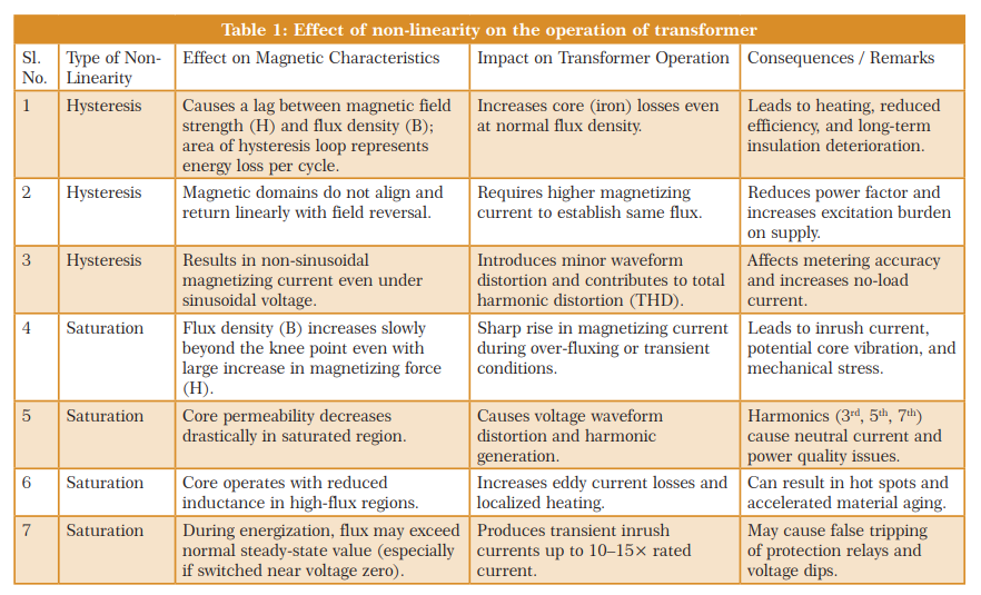
Core losses
Non-linear behaviour increases core losses, including:
- Hysteresis loss, which depends on the area of the hysteresis loop.
- Eddy current loss, which increases with higher harmonics in flux.
Harmonic distortion
When the magnetizing current becomes non-sinusoidal, it produces harmonic fluxes that can induce harmonic voltages in both primary and secondary windings. This leads to voltage waveform distortion, affecting the performance of connected equipment.
Voltage regulation and efficiency
Distorted flux and current lead to poor voltage regulation and reduced efficiency. Under heavy load or over-excitation, saturation further worsens regulation, resulting in voltage drops or waveform flattening.
Audible noise and vibration
The presence of harmonic components in the magnetizing flux leads to mechanical vibrations in the core laminations, producing audible noise (hum) commonly heard in power transformers.
Mitigation of Non-Linear Effects
Several design and operational techniques are used to minimize the impact of core non-linearity:
- Use of high-grade core materials: Silicon steel or amorphous alloys with high permeability and low hysteresis loss reduce non-linear behaviour.
- Proper core design: Operating the core below its saturation flux density ensures the B-H curve remains within the near-linear region.
- Controlled excitation: Avoiding over-voltage or DC bias in the excitation reduces the tendency toward saturation.
- Harmonic filters: In large transformers, harmonic filters may be used to limit the effects of magnetizing current harmonics on the power system.
Conclusion
Non-linearity in the transformer core has a profound impact on transformer operation. It leads to distortion of current and voltage waveforms, increased core losses, noise, and reduced efficiency. Understanding and mitigating these effects through appropriate material selection, core design, and operational control are vital for ensuring reliable transformer performance and power quality in electrical systems.

Bibhuti Bhusan Behera is an Assistant Professor at the Department of Electrical Engineering in Parala Maharaja Engineering College, Berhampur, Odisha.

Dr. Sarat Kumar Sahoo is a Professor at the Department of Electrical Engineering in Parala Maharaja Engineering College, Berhampur, Odisha.