

In recent years, the large growth in power demand and area constrains encouraging the wide application of series compensation on long transmission systems. But protection challenges associated with such lines with Metal Oxide Varistor (MOV) sought better algorithms to improve relay performance. To improve the stability, Single-Pole Tripping (SPT) and Auto Reclosing (AR) schemes are applied to high voltage transmission system. Proper phase selection is more important for such scheme for fast closing followed by tripping in line-to-ground fault case. On the other side fault type indicator has a greater importance on the distance relay operation so as to quickly identify and isolate the abnormality and restore the rest as soon as possible.
With the inception of fault in a system, it can be detected within quarter of cycle. But fault classifier may take several times or fail to classify due to instrument error, incorrect setting, classification algorithm, insufficient signal etc. So, the overall process will lead to unanticipated operation of distance relay. For different types of fault, the signals may appear differently, so considering that change, fault classification algorithms are set.
Several fault classification algorithms have been mentioned in the literature for series compensated and long transmission systems.
Discrete wavelet transformation and fuzzy can be applied to series compensated line to classify the fault type. For advanced series compensated line, a Support Vector Machine (SVM) based fault classification algorithm is used. As voltage-based classifiers have main drawback when strong source is connected with long line, the classifier operate incorrectly. So, only superimposed phase current based technique is suggested. Both superimposed phase voltage and current based techniques are also proposed by some experts.
Fault type can be easily detected by using sequence components i.e., whether there is a ground fault, phase-to-phase fault or three phase fault. Considering the sequence, components of current and voltage, a fault classification method is also proposed.
Also, fault type can be classified using the fault impedance. In the literature several integrated approach based methods are proposed to accurately discriminate the fault type. Another approach using sequence components applied to fuzzy integration is used to discriminate different fault types.
Another fuzzy based method is also proposed by some authors. Correlation analysis can be applied to achieve fast fault classification. Instead of using complicated logic, simple soft-processing based techniques can be used to accurately classify the type of fault. Simple max and min logical operators are applied to different rules to perform the task. Moving sum approach based fault detection is prescribed in some books. It is a very strong approach and it is not sensitive to frequency deviation, CT saturation, noise, transients etc.
In this article, a superimposed current sample based moving sum approach is presented for finding the accurate fault type in a series compensated, connected at middle of the line. Ground current is considered to distinguish between ground fault and phase fault. Based on rules, logical operators like max and min fault discrimination is done. The proposed method is very effective for changing system conditions, high resistance faults, CT saturation, different level of compensation, fault inception angle etc. The method is tested for a 400 kV series compensated line simulated using EMTDC/PSCAD.
Fault Classification Problems with Series Compensated Line
Most of the fault classification algorithms for long transmission lines are either based on sequence components or phase quantity may provide correct results for wide system variations, if designed properly. But the available methods may mal-operate when applied to series compensated lines because of several reasons.
With the initiation of fault decaying, DC is always present in the current signal during the transient period as shown in Fig.1. More than two cycles are required to damp out these components.
Further any disturbance in a series compensated line can give rise to sub-synchronous frequency components in the fault current.
Digital filters like least square, reiterative DFT can able to provide fundamental components but the overall process will take much time.
High current fault in a series compensated line is not an issue. But as the MOV is self extinguishing in nature, transients are generated with its reinsertion, which can influence the relaying decision.
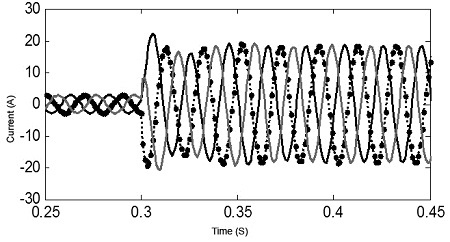
Fig. 1. Current waveform for three phase fault
With low current faults voltage and current inversion problems may arise in a series compensated lines. This is not at all a problem with series capacitors placed at the middle of the line. Generally, line end capacitor creates more problems than the capacitor placed at the middle.
For fault at different positions (before and after capacitor), the current level may be of the same order in a line with series capacitor placed at central location.
Hence, the overall performance of fault classification algorithm depends on position of series capacitor, MOV operation, phasor estimation, fault location, fault resistance, type of fault etc.
So, within half a cycle discriminating the type of fault holding these challenges is a crucial task for the relaying algorithm.
Moreover, simplicity of the method is also an important factor to avoid large mathematical calculations.
Hence, a fault classification technique is proposed in this article, which will enable to look out the above mentioned issues.
Proposed Superimposed Current Based Moving Sum Approach
Fault detection using superimposed current phasors is a very strong approach.
But classification of different fault types is very difficult mainly between line-to-ground fault and double-line-to-ground fault at different positions for a series compensated line as shown in Fig. 2.
The system data are provided in the Appendix. The current data is collected from the output of CT having ratio 1600/5.
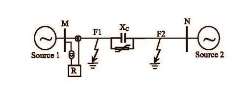
Fig. 2: The three phase power system model…
For an AB-G fault occurred at 0.3 sec after 149 km with 80 ohm fault resistance from the capacitor, the superimposed current based method provides almost same output for AB-G and Ag fault, which is cleared from Fig.3 (a) and (b).
So, there is a chance of mal-operation of the relay.
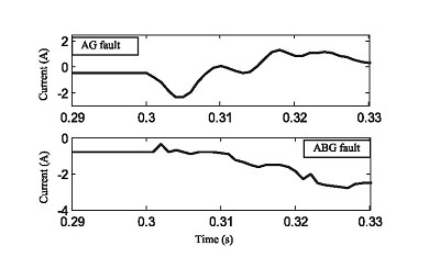
Fig. 3. Current waveforms for (a) ab-g fault…
(b) ab fault…
For a wide range of system variation, it is very difficult for any method to offer correct result. Selecting the threshold value is also very difficult. Instead of using very complicated mathematical calculations or any integrated approach, a simple rule based fault classification approach is provided as described below.
A: Description of Proposed Method
After the detection of fault superimposed current sample value for each phase A, B, C are calculated.
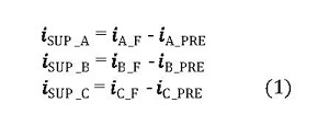
A short window is considered for calculating the moving sum of each phase superimposed current data.
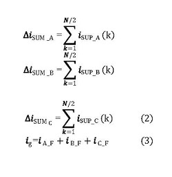
Where N = no. of samples per cycle. ig is the ground current.
To obtained accurate fault type within half-a-cycle separate rules are framed for each fault case. As transients in the current signals are present during initial period, any logic will not provide consistent result. So, the logical operators max and min are used. After the detection of fault, the moving sum of three phases superimposed currents are calculated. From the calculated values half cycle samples are considered.
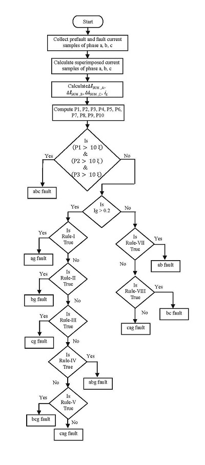
Fig. 4: Flow diagram of proposed fault classification method…
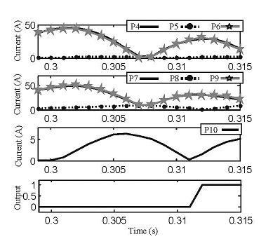
Fig. 5: Plots for a-g fault at 90 km from relay with Rf = 100 ohms…
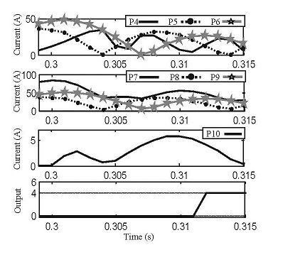
Fig. 6: Plots for ab-g fault at 90 km from relay with Rf = 100 ohms…
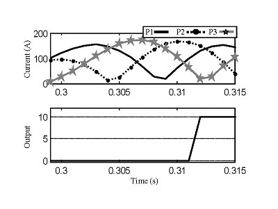
Fig. 7: Plots for abc fault at 1 km from capacitor…
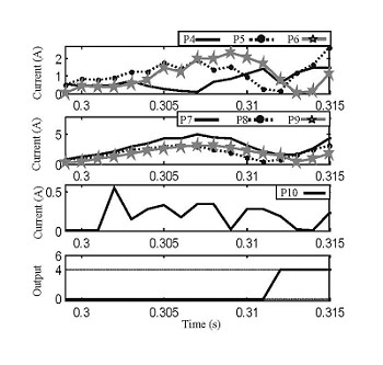
Fig. 8: Plots for ab-g fault at 297 km with Rf = 200 ohms…
Then based on the rules their maximum vales are calculated. If the maximum value is minimum of the compared values then based on rules the fault type is declared. i_g is considered to distinguish between ground fault and phase-to-phase fault. After going for several cases and system conditions it is observed that a minimum value of current flowing through the ground during balance fault and phase-to phase fault. So, a threshold limit α of 0.2 amps in the ground is considered to distinguish between ground and ungrounded fault. Similarly, to distinguish the different types of fault, a minimum limit value is fixed i.e., ξ which can be considered as CT secondary current. The algorithm first checks after the fault detection, whether it is a three phase fault or not. If not, then the neutral current is calculated to detect other fault type.
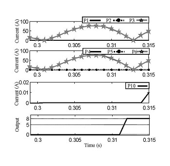
Fig. 9: Plots for bc fault at 295 km with Rf = 1 ohms…
B: Operators used in proposed fault classification rules:
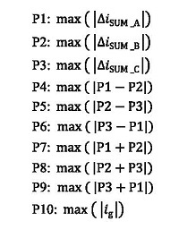
C: Rules for different fault types:
Rule – I:
If (P10 > α) &
(min (P4, P5, P6) = P5) & (min (P7, P8, P9) = P8)
Then AG fault.
Output: 1
Rule – II:
If (P10> α) &
(min (P4, P5, P6) = P6) & (min (P7, P8, P9) = P9)
Then BG fault.
Output: 2
Rule – III:
If (P10> α) &
(min (P4, P5, P6) = P4) & (min (P7, P8, P9) = P7)
Then CG fault.
Output: 3
Rule – IV:
If (P10>α) & (min (P4, P5, P6 ) = P4) & (max (P7, P8, P9) = P7)
Then ABG fault.
Output: 4
Rule – V:
If (P10 > α) & (min (P4, P5, P6) = P5) & (max (P7, P8, P9) = P8)
Then BCG fault.
Output: 5
Rule – VI:
If (P10 > α)
(min (P4, P5, P6) = P6) & (max (P7, P8, P9) = P9)
Then CAG fault.
Output: 6
Rule – VII:
If (P10 < α) &
(min (P1, P2, P3) = P3) & (min (P4, P5, P6) = P4)
Then AB fault.
Output: 7
Rule – VIII:
If (P10 < α) &
(min (P1, P2, P3) = P1) & (min (P4, P5, P6) = P5)
Then BC fault.
Output: 8
Rule – IX:
If (P10 < α) &
(min (P1, P2, P3) = P2) & (min (P4, P5, P6) = P6)
Then CA fault.
Output: 9
Rule – X:
If (P1 > 10 ξ) & (P2 > 10 ξ ) & (P3 > 10 ξ)
Then ABC fault.
Output: 10
The flow diagram of the proposed method is shown in Fig.4.
Procedure Evaluation
To observe the performance of proposed algorithm for various fault types and system conditions, data are generated by EMTDC/PSCAD software and input to MATLAB. The voltage magnitude ratio (h) and load angle (δ) are considered as 1, 10°. Sampling rate of 1 kHz is selected for the system. Using three phases superimposed moving sum current and ground current based on rules fault class is declared.
A: Results for fault before series compensation:
An A-G and AB-G fault cases are simulated from 90 km from relay end with fault resistance (Rf) is considered as 100 ohms. Fault initiation occurs at 0.3 sec. Fig. 5 illustrates the plots for A-G fault. From the figure, it is clear that P5 and P8 have minimum values with P10 greater than α, so the output comes out as 1 indicates A-G fault by the proposed method.
This implies that even for normal line also, this will provide correct result. Similarly in Fig. 6, an AB-G fault case is shown. As all the conditions satisfied, the output comes out at 4.
It is clear from the two results that as the same operators are used to distinguish between single-line-to-ground fault and double-line-to-ground fault, and because of the distinct signals there is not at all a chance of mal-operation of the proposed algorithm. To test the accuracy of the proposed method, several other cases are also simulated below.
B: Results for fault close to series compensation:
A fault case is simulated for three phase fault 1 km after the series compensation. From Fig. 7, it is clearly understood that as the P1, P2, and P3 are simultaneously greater than 10 ξ which indicates there is a balance fault and the output comes out as 10 i.e., ABC fault.
C: Results for far end high resistance fault:
Generally, far end faults are difficult to detect and classify if going through high resistance as the level of fault current is very less. To check the performance of proposed method, a case is simulated for AB-G fault at 297 km from relay end with Rf of 200 ohm.
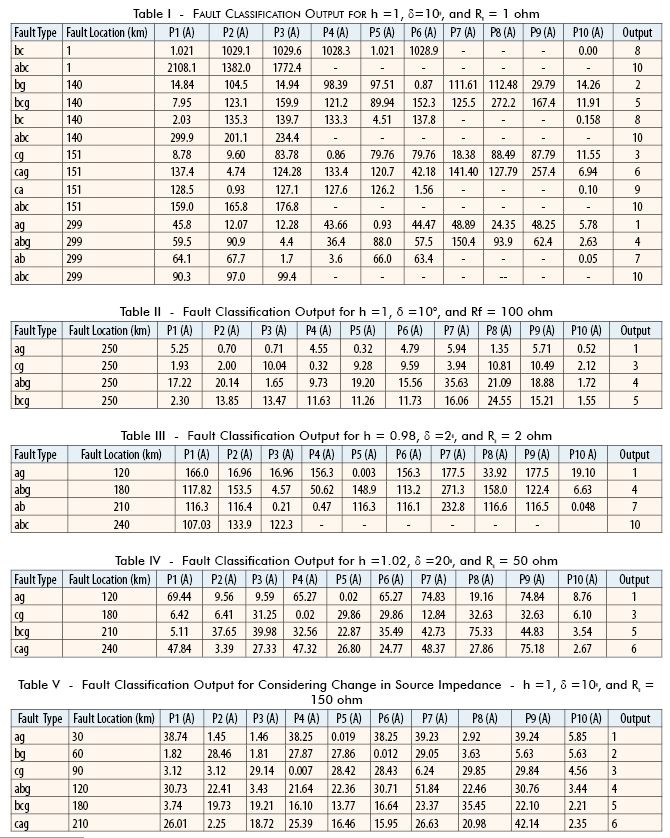
In Fig.8, the output is shown, which indicates the accuracy of the proposed method. To observe the performance of the proposed method, wide variation in fault resistance and fault locations are considered and the simulation results are provided in Table I and II.
D: Results for faults during changing system condition:
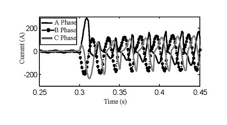
Fig. 10: CT saturation waveform.
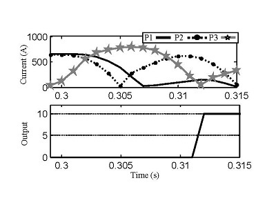
Fig. 11: Response of proposed method during CT saturation…
System conditions such as loading level, voltage level, source impedances change frequently. Protective algorithm should be of adaptive nature or designed considering the most expected variations so as to avoid mal-operation. A fault case is simulated considering load angle (δ) as 2° and voltage magnitude ratio (h) as 0.98. An bc fault is simulated at 295 km from relay with a fault resistance of 1 ohm.
The current in the ground is very less. So it is detected as a phase-to-phase fault. According to rules for ab fault P3 and P4 should have minimum value which is true as shown in Fig.9. So the output is 7.
Different fault cases with fault resistances and large change in system conditions are simulated and result of each shown in Table III and IV.
To observe the effect of source impedance variation on the proposed method different fault cases are simulated by increasing the source to twice of its original value. From Table V it is cleared that the influence of source impedance variation is negligible on the proposed algorithm.
Effect of CT Saturation
A short circuit fault very near to relay may cause CT saturation. During saturation, secondary current of CT is severely distorted which results in phase shift between unsaturated and saturated current waveform.
Also, the presence of large decaying dc component creates error in phasor estimation. The current waveform for CT saturation period is shown in Fig.10.
The response of proposed method for such a condition is tested by creating a three fault at 1km from relay end.
The burden resistance of CT is taken as 30 ohms. From Fig. 11, it is understood that even for CT saturation also the method holds the accuracy.
Conclusion
A methodology to classify the ten fault types within half-a cycle without using any phasor estimation process considering only moving sum of superimposed data for a series compensated line has been presented in this article. The proposed method is able to discriminate between line-to ground and double-line-to ground faults irrespective of their position, fault resistance and position of series compensation.
Also, influence of change-in source impedance and loading level have less impact on the proposed method. The classification of different fault types is also possible during CT saturation, which is evident from the results.

If you want to share thoughts or feedback then please leave a comment below.


 Meters")
