Electrical fires in electrical installation may be broadly caused by:
- Over currents (overloads and short circuits)
- Harmonics
- Earth fault
- Electric arcs in cables and loose Connections
- Failure of protection device or Wrong selection of protection device
- Wrong selection of cables or wires
- Mismatch of illumination fittings rating and lamps used
- Use of extension cord for heaters or any other heavy loads
- Use of outlived (outdated) or damaged equipments
- Over voltages (Lightning ) & arcing ground
- Consumer has become prosumer
- Inadequate design for earthing / grounding
- Improper or No verification and testing (commissioning or periodical)
A short circuit is an abnormal connection between two nodes of an electric circuit intended to be at different voltages. This results in an electric current limited only by the equivalent resistance of the rest of the network which can cause circuit damage, overheating, fire or explosion (refer figure 1).

This high current generates high heat and presence of fuel or any other flammable materials may result in the fire hazard as governed by fire triangle in figure 2.

The harmonic current alone in the neutral wire can be up to 1.7 times larger than the full rated current of the power wiring. This causes the overheating of the system and overheating of the equipment used in the system, which can lead to the occurrence of fire in the system and wiring.
Earth Fault is an inadvertent fault between the live conductor and the earth. When earth fault occurs, the electrical system gets short-circuited and the short-circuited current flows through the system. The fault current returns through the earth or any electrical equipment, which damages the equipment.
An arc fault is a high power discharge of electricity between two or more conductors. This discharge generates heat, which can break down the wire’s insulation and trigger an electrical fire. Arc faults can range in power from a few amps up to thousands of amps, and are highly variable in strength and duration.
There are always chances of suffering an electrical power system from abnormal over voltages. These abnormal over voltages may be caused due to various reasons such as, sudden interruption of heavy load, lightening impulses, switching impulses etc.
These over voltage stresses may damage insulation of various equipments and insulators of the power system. Although, all the over voltage stresses are not strong enough to damage insulation of system, but still these over voltages also to be avoided to ensure the smooth operation of electrical power system.
Main Causes Of Electrical Fire In Residential & Commercial Buildings
Electrical fires very often take place in residential sector. This is because most of the people do not account for the rating of the appliances while placing or connecting them. Being an individual, most of us are not aware about the parameters we need to consider while purchasing the product. The only thing that people look for is the cost effectiveness which in turn leads to extreme situation resulting in electrical fires. Major reason for electrical fire in LV system is Short Circuiting i.e., flowing of current through unintended path. It happens mainly due to degradation of insulation
As the wire gets old, the insulation gets degraded, due to which there is a chance of short circuiting (figure 3) & this may lead to fire.

Other Causes of Electrical Fire (Besides Short Circuit & Insulation Failure)
- Outdated Appliances: Electrical fire can be caused even by small sparking. So, the first and foremost cause of electrical fire is the use of outdated appliances. All the electrical appliances have certain years of life after that their output keeps on degrading. Several times this leads to malfunctioning of the electrical appliances resulting in heavy power losses and sparking in the switchboard. This when not controlled can burn the appliance due to prolonged heating causing electrical fire.
- Severed Wires & Overload Outlets: Another cause of electrical fire is the use of severed electrical cables. These days many appliances are cordless but the major applications are still wired. Overloaded outlets or faulty wires can cause electrical fire. Sometimes due to rough and tough use of electrical appliances, there are severe chances of worn and torn of the cord. A small and wide application is the mobile charger. The cable sometimes breaks from the either end and still we continue using it because it is still serving our purpose. But this leads to sparking, burning of the appliance and hence the fire. (Refer figure 4)

- Proximity of Appliances: Especially in residential areas, many appliances are kept at very minimum distance from each other. Due to electric fire in any of the appliances, the other nearby kept appliances also come under the action of the fire. Also, flammable materials such as curtains, rugs etc. cause rapid expansion of fire resulting in critical situation.
- Improper Rating of Appliances: The rating of the appliances like bulbs must be chosen smartly ensuring similar recommended wattage for that bulb holder. Installing a bulb of high wattage that is too high for the holder can lead to electrical fires.
- Poor Grounding (Earthing): When proper grounding is not provided in the complete network this might also result in electrical fires apart from electrical shocks.
- Heating Appliances: In winter season, the heating appliances are more in use. So, many numbers of electrical fires take place during that time of the year. The major issue is covering the appliances such as lampshade for making it more attractive. The appliances when covered produce more heat that can ignite the paper or cloth kept over the appliance. This will also lead to electric fire and can spread across rapidly because the lamps are generally placed in the living room containing more combustible items.
- Blown Fuses or Faulty MCB: Blown Fuses and non-operation of circuit breaker quite often is also a major concern. When any kind of faults take place, the circuit breakers or the fuse are the first to act. The blown fuse must be kept at priority for rectification since that might lead to electrical fire when not restored till the next fault. The fuses and circuit breakers just isolate us from the faulty circuit but the fault must be identified and rectified. If not done so, this might lead to heavy destruction. (Refer figure 5)

Role of Adequate Earthing in Prevention of Hazards
Grounding/ Earthing means making a connection to the general mass of earth. The use of grounding is so widespread in an electric system that at practically every point in the system, from the generators to the consumers’ equipment, earth connections are made.
There are two types grounding (Refer figure 6):
- Neutral Grounding
- General (Equipment) Grounding

The objectives of General Grounding system include:
- To provide a low resistance return path for fault current which further protects both working staff and equipment installed in the premises (Refer figure 7).
- To prevent dangerous GPR with respect to remote ground during fault condition.
- To provide a low resistance path for power system transients such as lightning and over voltages in the system.
- To provide uniform potential bonding /zone of conductive objects within substation to the grounding system to avoid development of any dangerous potential between objects (and earth).
- To prevent building up of electrostatic charge and discharge within the substation, which may results in sparks.
- To allow sufficient current to flow safely for satisfactory operation of protection system.
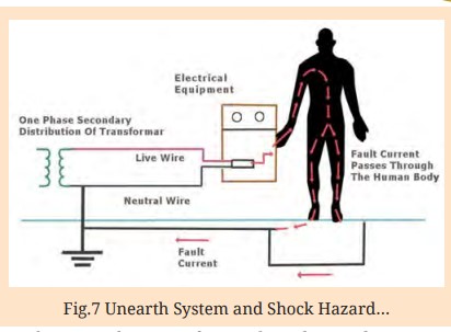
The main objective of grounding electrical systems is to provide a suitably low resistance path for the discharge of fault current, which ultimately provides safety to working personnel and costly installed equipments in the substation.
In order to understand the role of adequate earthing design, abstract of IS 3043 are given below:
Basic Objective of System Earthing
- Earthing of system is designed primarily to preserve the security of the system by ensuring that the potential on each conductor is restricted to such a value as is consistent with the level of insulation applied.
- From the point of view of safety, it is equally important that earthing should ensure efficient and fast operation of protective gear in the case of earth faults.
- The system earth-resistance should be such that, when any fault occurs against which earthing is designed to give protection, the protective gear will operate to make the faulty main or plant harmless. In most cases, such operation involves isolation of the faulty main or plant, for example, by circuit-breakers or fuses.
Equipment Earthing
The basic objectives of equipment grounding are:
- To ensure freedom from dangerous electric shock voltages exposure to persons in the area;
- To provide current carrying capability, both in magnitude and duration, adequate to accept the ground fault current permitted by the over current protective system without creating a fire or explosive hazard to building or contents; and
- To contribute to better performance of the electrical system.
Fire Due to Harmonics
Wiring of the 3-phase building consists of 3 phase conductors, a ground conductor, and one neutral conductor. The loads which are single-phase are connected in between the different phase conductors and the neutral conductor. The neutral conductor serves as the “common” return for all of the single-phase load currents and these load currents “cancel out” in the neutral wire. (Refer figure 8)

The harmonic currents which are created by different non-linear system generates a substantial amount of 3rd harmonic current and due to the mathematical phase properties of odd harmonics, third harmonic currents add instead of cancelling out each other on the neutral wire. Therefore, the neutral wire needs to carry much higher currents than it is designed for. The fact is that the harmonic current alone in the neutral wire can be up to 1.7 times larger than the full rated current of the power wiring. This causes the overheating of the system and overheating of the equipment used in the system that can lead to the occurrence of fire in the system and wiring.
Over Voltage & Lightning and Fire Hazard
Over voltages are produced in the system due to external causes or internal causes. Internal over voltages are caused by changes in the operating conditions of the power system.
These can be divided into two groups as below:
Switching over voltages or Transient over operation voltages of high frequency:
This is caused when switching operation is carried out under normal conditions or when fault occurs in the network. When an unloaded long line is charged, due to Ferranti Effect the receiving end voltage is increased considerably resulting in over voltage in the system.
Similarly, when the primary side of the transformers or reactors is switched on, over voltage of transient nature occurs.
Temporary over voltages:
These are caused when some major load gets disconnected from the long line under normal or steady state condition.
Over Voltage due to External Causes:
This cause of over voltage in power system is the lightning strokes in the cloud. This takes the form of a surge and has no direct relationship with the operating voltage of the line.
There are two types of Lightning Strokes:
- Direct lightning strokes
- Indirect lightning strokes
Fire Due To Lightning
Lightning passing through a house will often ‘branch’ and utilize more than one path to ground at a time. It can also jump through the air from one conductive path to another in what is called an Uncontrolled flash.
For example, lightning may first connect to electric lines in the attic/ambit of a house, then jump to better-grounded water pipes on the first or second floor. Lightning can connect to gutters, then jump to a window frame as a ‘stepping stone’ to the electrical system or water pipes. All or parts of bolts have been seen jumping from wall outlets to sink faucets/ taps and even across rooms.
Lightning current will produce significant damage to a house that is not equipped with a good protection system. Professionally-installed lightning protection systems are expensive and the risk of a direct strike is low, so most homes do not have them. (Figure 9 and 10 may be referred).
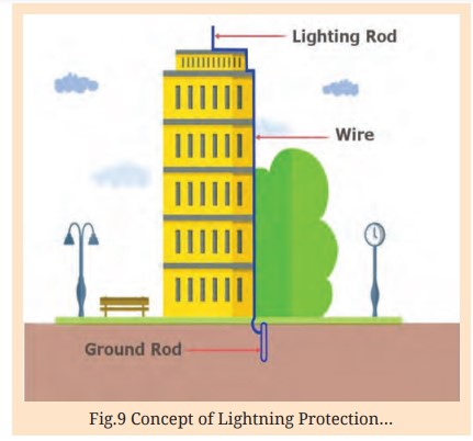

Lightning presents three main hazards to a house that is hit directly:
- Fire Danger: The biggest danger lightning poses to a house is fire. Wood and other flammable building materials can easily be ignited anywhere an exposed lightning channel comes in contact with (or passes through) them. It is most common for lightning to start a fire in the attic or roof of a house, as the channel usually has to pass through some of the structural material in the roof before it can reach a more conductive path such as wiring or pipes. When lightning current travels through wires, it will commonly burn them up – presenting a fire ignition hazard anywhere along the affected circuits.
- Power Surge Damage: If lightning chooses any of the home’s electrical wiring as its primary or secondary path, the explosive surge can damage even non-electronic appliances that are connected. Even if most of the lightning current takes other paths to ground, the home’s electrical system will experience enough of a surge to cause potentially significant damage to anything connected to it, electronics in particular.
- Shock Wave Damage: Another major source of damage from lightning is produced from the explosive shock wave. The shock waves that lightning creates is what produces the thunder that we hear, and at close range, these waves can be destructive. Lightning can easily fracture concrete, brick, cinderblock and stone. Brick and stone chimneys are commonly damaged severely by lightning. Lightning’s shock waves can blow out plaster walls, shatter glass, create trenches in soil and crack foundations. Shrapnel is a common secondary damage effect, with objects sometimes found embedded in walls.
Fire Due to Arc Flash
Apart from above causes of hazards, there is one more hazard called Arc-flash hazard (Refer figure 11). An arc flash is a phenomenon where a flashover of electric current leaves its intended path and travels through the air from one conductor to another, or to ground.

The arc flash in an electrical fault produces the same type of light radiation from which electric welders protect themselves using face shields with dark glass, heavy leather gloves, and full-coverage clothing. The heat produced may cause severe burns, especially on unprotected flesh.
The arc blast produced by vaporizing metallic components can break bones and damage internal organs. The degree of hazard present at a particular location can be determined by a detailed analysis of the electrical system. Arc flash temperatures can reach or exceed 35,000 °F (19,400 °C) at the arc terminals.
The massive energy released in the fault rapidly vaporizes the metal conductors involved, blasting molten metal and expanding plasma outward with extraordinary force. A typical arc flash incident can be inconsequential but could conceivably easily produce a more severe explosion. The result of the violent event can cause destruction of equipment involved, fire, and injury not only to an electrical worker but also to bystanders. During the arc flash, electrical energy vaporizes the metal, which changes from solid state to gas vapour, expanding it with explosive force. For example, when copper vaporizes it suddenly expands by a factor of 67,000 in volume.
In addition to the explosive blast, called the arc blast of such a fault, destruction also arises from the intense radiant heat produced by the arc. The metal plasma arc produces tremendous amounts of light energy from far infrared to ultraviolet. Surfaces of nearby objects, including people, absorb this energy and are instantly heated to vaporizing temperatures. The effects of this can be seen on adjacent walls and equipment – they are often
The following are among the most common areas where arc flashes occur:
- Electrical Panels
- Switchboards
- Motor Control Centers
- Transformers
- Damaged Wires
- Metal Clad Switch Gears
- Fused Disconnects
Fire Due To Arcing Ground
Arcing ground is the surge, which is produced if the neutral is not connected to the earth. The phenomenon of arcing ground occurs in the ungrounded three-phase systems because of the flow of the capacitance current. The capacitive current is the current flow between the conductors when the voltage is applied to it. The voltage across the capacitances is known as the phase voltage. During the fault, the voltage across the capacitance reduces to zero in the faulted phase, while in the other phases the voltage is increased by the factor of √3 times.
When SLG fault happens, the capacitive current over 4 to 5 ampere flows through the fault gives rise to an arc in the ionised path of the fault. With the formation of the arc, the voltage across it becomes zero, and therefore the arc is extinguished. The potential of the fault current restored due to which the formation of a second arc takes places. The phenomenon of intermitting arcing is called the arcing grounding. (Refer figure 12)

The alternating extinction and re ignition of the charging current flowing in the arc build up the potential of the other two healthy conductors due to the setting of the high-frequency oscillations. The high-frequency oscillations are superimposed on the network and produce the surge voltage as high as six times the normal value. The overvoltage damages the healthy conductor at some other points of the system and may become the cause of fire.
Consumer Has Become Prosumer- Solar Pv Rooftop
Solar energy has become the most popular renewable energy source wherein energy is extracted directly from sun using photo-voltaic (PV) modules.
Though SPV are basically either Grid connected or Off grid, following four configurations are commonly used for solar PV system:-
- Grid connected SPV system without battery storage
- Grid connected Net Metering system with Battery storage- system disconnected from Grid in the event of use of battery at the time grid failure
- Off-grid standalone SPV system (micro grid) with battery- system supplying power to a cluster of houses
- Off grid dedicated standalone SPV system used for independent houses, street lights, pump sets etc.
In first three systems, there is a requirement of inverter while the fourth system may provide DC or AC based on the user requirement.
The inverter is nothing but power electronics converters which also works as voltage regulators for output power but may develop harmonics in output voltage during conversion from DC to AC which would be injected in to the grid leading to various power quality problems in the grid.
In a grid connected SPV system there are two challenges related to power quality (PQ) – one is at source end like power factor, reactive power compensation, harmonics and voltage regulations and the other is handling the PQ issues arising out of the nonlinear loads on this PV system which can generate sag swells and switching transients in the network.
Conventional SPV systems operate at unity power factor, regardless of reactive power needs of the utility network. Effectively, such PV system when connected to grid, reduces the power factor at the load end, as the part of the active power is met through SPV, (where SPV capacity is less than the load at consumer end), and grid is then supplying balance active power, but maintains the same amount of reactive power to the connected load.
Nowadays consumers have become prosumer i.e., consumers are also producing energy using renewable energy system as shown in figure 13. The renewable energy systems (SPV or Windmills) operate at unity power factor. Such systems when connected to the grid, leads to a lower power factor at the load end, as the part of the active power (otherwise provided from the grid) is met through the source of renewable energy.

But since the power supply capacity of renewable energy systems is less than the load at the consumer end, and the grid supplying balance active power while maintaining the same amount of reactive power to the connected load.
The poor PF in turn leads to problems such as heating of components in the electrical system thereby increasing the risks of failure or fire.
Verification (Inspection & Testing) of Installation
As per IS 732 every installation or change (namely addition or changes) to an existing installation must be verified during erection, as far as reasonably practicable, and on completion, before being put into service by the user.
Initial verification shall include comparison of the results with relevant criteria to confirm that the requirements this standard have been met.
Precautions shall be taken to ensure that the verification shall not cause danger to persons or livestock and shall not cause damage to property and equipment even if the circuit is defective.
For an addition or alteration to an existing installation, it shall be verified that the addition or alteration complies with this standard and does not impair the safety of the existing installation.
Inspection shall precede testing and shall normally be done prior to energizing the installation. The inspection shall be made to confirm that electrical equipment which is part of the fixed installation is:
- In compliance with the safety requirements of the relevant equipment standards. This may be ascertained by examination of the manufacturer’s information, marking or certification.
- Correctly selected and erected according to this standard and to the manufacturer’s instructions;
- Not visibly damaged so as to impair safety.
- Inspection shall include at least the checking of the following, where relevant:
- Method of protection against electric shock
- Presence of fire barriers and other precautions against propagation of fire and protection against thermal effects
- Selection of conductors for current-carrying capacity and voltage drop
- Choice and setting of protective and monitoring devices
- Presence and correct location of suitable isolating and switching devices
- Selection of equipment and protective measures appropriate to external influences
- Neutral and protective conductors correctly identified
- Single-pole switching devices connected in the line conductors (
- Presence of diagrams ,warning notices or other similar information
- Identification of circuits, overcurrent protective devices, switches, terminals, etc
- Adequacy of connection of conductors
- Presence and adequacy of protective conductors, including main and supplementary equipotential bonding conductors
- Accessibility of equipment for convenience of operation, identification and maintenance
Inspection shall include all particular requirements for special installations or locations.
The following tests shall be carried out where relevant and should preferably be made in the following sequence:
- Continuity of conductors
- Insulation resistance of the electrical installation
- Protection by SELV, PELV or by electrical separation
- Floor and wall resistance/impedance
- Automatic disconnection of supply
- Additional protection
- Polarity test
- Test of the order of the phases
- Functional and operational tests and
- Voltage drop
In the event of any test indicating failure to comply, that test and any preceding test, the results of which may have been influenced by the fault indicated, shall be repeated after the fault has been rectified.
Conclusion (Prevention Recommendations & List of Tests & Safety Tips)
- Adequate designing of grounding systems and lightning systems will help in mitigating or eliminating fire and accident hazard. It is pertinent to mention here that one location one earthing concept should be followed. Proper bonding of all extraneous conductive parts needs special attention including auxiliary bonding system, if needed.
- Electrical fires are more likely to be due to the failures of electrical connectors and terminal boards, because there are no Protective systems to detect bad contacts. Fire due to short circuit which happens due to a defect in the protective system or delay in the operation of protective system or failure of insulation needs special attention.
- Ensure that current ratings of wires, cables and accessories are equal to or higher than the maximum possible loads. Also resistance of wires should not be more than the value recommended by IS codes.
- Ensure that all wires and cables are protected by fuses / MCB. Also proper type of MCB needs to be used in the circuit.
- Ensure that switch-boards, terminal boards, joints, etc. are not fixed close to combustible materials.
- In the absence of infrared cameras, carry out at least close visual monitoring of all bolted or crimped joints.
- Use only those electrical equipment, cables/wires, MCB and accessories which comply with relevant Indian Standards.
- The outdated appliances must not be used. Faulty wires must also be replaced.
- The extension cords must only be used for temporary purpose that too they should match the amperage of the appliance. Otherwise, the appliance must be directly plugged into the outlet.
- Flammable materials must be kept away from the electrical outlet or the electrical appliances so as to avoid the spread of fire.
- Cords or cables must not be laid under rugs or furniture.
- Whenever a burning smell is sensed, immediately the cause must be identified so as to avoid any further disaster to take place.
- Electrical appliances must not be covered especially when in use so that production of heat is avoided.
- Appliances must be used with proper care for long life, less faults and hence less fires.
- Regular maintenance & Condition monitoring testing of all the equipments in the system must be done periodically to avoid any hazards. The list of test to be conducted are summarised in the table below.


Last but not the least a poster depicting the sources of hazards and prevention methods (created for general awareness) is shared below as part of conclusion or findings of my research.
References
[1] Manual on,” Grounding of A C Power Systems,” Publication No
339, C.B.I.P. New Delhi.
[2] IS 3043-2018,Indian Standard Code of Practice for Grounding.
[3] CEA ‘Measures relating to Safety and Electric Supply’ and
‘Technical Standards for Construction of Electrical Plants and
Electrical Lines and Connection to Grid under Regulations 2010.
[4] IS 732: Code of Practice for Electrical Wiring Installations
[5] IS/IEC 62305 – Protection Against Lightning
[6] National Building Code 2016
[7] Electrical Installation Guides of ABB & Schneider

Dr. Rajesh Kumar Arora obtained the B. Tech. & Master of Engineering (ME) degrees in Electrical Engineering from Delhi College of Engineering, University of Delhi, India in 1999 and 2003 respectively. He completed his PhD in grounding system design from UPES, Dehradun. He is also a certified Energy Manager and Auditor and has worked in 400kV and 220kV Substation for more than 14 years in Delhi Transco Limited (DTL). He has also worked as Deputy Director (Transmission and Distribution) in Delhi Electricity Regulatory Commission (DERC) for 03 years and 06 months. He has also given his contribution in the OS department of DTL for more than 2 years and rendered his services in the SLDC of Delhi Transco Limited (DTL) also. Presently he is working in D&E (Design and Engineering) department of DTL. His research interests include high voltage technology, grounding system, protection system, computer application and power distribution automation.


