

Need for Earthing
Equipment in automotive industries where control panels are situated are of high frequencies which when interfere with other electrical components cause malfunction. Generally, devices like controllers, communication devices and digital measuring devices when exposed to electromagnetic interference fail to provide effective output & pose threats of electric shocks during fault conditions.
During fault condition, high current flows through the system and there is a possibility that current does not flow through its intended path instead flows through metallic body of machines or panel. When a person comes in contact with such an electric circuit or source of electric energy, he/she is prone to an electric shock. An electric shock may result in either no injury at all or one which can prove to be fatal, causing death. Possibilities of shock increases if the electrical system is not well protected or insulated from its high voltage environment.
In order to safeguard operating personnel and system from:
- Electromagnetic interference due to high frequency components and
- Electric shocks.
It is necessary to provide a path to divert the fault current, this calls for the arrangement of earthing systems.
What is Earthing?
As per IEEE 80-2000, a conducting connection, whether intentional or accidental, by which an electric circuit or equipment is connected to the earth or to some other conducting body of relatively large extent that serves in place of the earth is called Earthing.
A safe grounding must fulfil the below mentioned objectives:
- To provide means of carrying electric currents to earth under normal and fault conditions without exceeding any operational limits or affecting service continuity.
- To assure that a person in vicinity of grounded facilities is not exposed to the danger of critical electric shock.
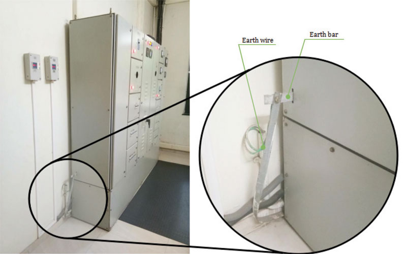
Earthing of Electrical Panels
When earthing an electrical panel, the following applies:
Earthing a main panel: The ground bar is bonded internally which must be of proper dimensions as per IS or NEC norms and to be earthed at two ends.
Earthing a sub-panel: Sub-panels are grounded through the cable that provides the secondary-feed circuit power. A secondary-feed cable will have two insulated power conductors, one insulated neutral conductor and one ground wire. The ground wire is bonded at the main panel to the ground system. The secondary-feed wiring type and size will depend on the specific application and the applicable local building codes.

What should be measured at earthing point?
Earth Resistance: A very few standards mention the exact value of ground resistance, ideally the value must be zero ohms. Standards like IEEE recommend a ground value of less than 5.0 ohms.
The earth resistance must be measured periodically to make certain that our system is grounded properly and ensures human safety during faults, because if ground resistance is high fault currents will flow through human body when in vicinity.
Earth Voltage: It is recommended that the earth must be at zero potential. But due to neutral connection, a small amount of earth to neutral voltage is present. It must not exceed more than 2V, where 5V is the upper limit leading to circulation of ground currents.
How will you test earth resistance?
There are different methods of testing earth resistance, some of the popular methods are:
- Fall-of-Potential method
- Dead earth method
- Clamp-on test method.
The first method is commonly used and gives accurate results than the dead earth method which is not so common and practised only when a quick-check is required. The last method is generally not recommended by experts due to its limitations.
The resistance to earth through an electrode can be easily calculated by Ohm’s Law, ![]()
Where ![]()
and
r = Resistivity of earth in ohm-cm
l = length of conducting path
A = Area of cross-section
Fall-of-Potential Method
The most common method is the Fall-of-Potential Method. A rigorous procedure is to be followed to accurately measure earth resistance. According to the area or land mass and other factors the task can be tiresome and lengthy. Dodge in carrying out the process may lead to inherent errors.

To measure the earth/ground resistance of a single earth electrode at “Rod 1”, a current is forced to flow through Rod 1 by driving an auxiliary test probe – current probe or Rod 2 into the ground at a certain distance away from the Rod 1 electrode and connecting the Rod 2 to a current source. In this case the ground resistance test meter is the current source which generates an alternating current. An electrical circuit is formed between Rod 1 and Rod 2 with current flowing between them in the ground.
At points between Rod 1 and Rod 2 electrical potentials are created; there is a resistance path between Rod 1 and Rod 2 so a voltage will develop at points along this path due to the current. A second auxiliary test probe – potential probe or Rod 3 is driven into the ground between Rod 1 and Rod 2 to measure electrical potential (voltage). This voltage varies along the path between Rod 1 and Rod 2; maximum voltage occurs at Rod 1 and zero at Rod 2. Current is measured between points 1 and 2 and voltage across point 1 and 3. If the position of Rod 3 is changed in a straight line then different values of voltage are obtained. Using Ohm’s law one can calculate different values of earth resistance. When these values are plotted on a graph of distance versus resistance a curve is obtained, as shown in figure 5. The inferences are as follows:
- Value of resistance increases gradually as Rod 3 is moved away from Rod 1 but at a certain point this resistance is almost constant (~20Ω).
- Value of resistance increases sharply after a certain point where Rod 3 is near to Rod 2.
In order to achieve optimum results, the three electrodes must be well placed and the distance between earthing electrode and potential probe must be 61.8% of the distance between earthing electrode and current probe. This concept comes from a careful mathematical development particularly for the case of a hemispherical electrode, published by Dr. G.F. Tagg in 1964.
Dead Earth Method
In areas where use of ground electrode is impracticable, the 2-point or Dead earth method can be used. With this method, the resistance of two electrodes in series is measured by connecting P and C terminals together to reference ground electrode; and E connected to a separate all-metallic grounding point (water pipe or ground steel rods of building) as reference earth electrode, shown in figure 6. This is the simplest method to obtain earth resistance but not as accurate as Fall-of-Potential method and should only be used as last resort.
Agam AET-23
The Agam earth tester, AET 23 is capable of performing measurements of both earth resistance in ohms and also calculates AC earth voltage from 0-200V. Earth resistance testing can be performed across three ranges: 0-20 Ohms, 0-200 Ohms and 0-2000 Ohms.
It is handy and very simple to use; it can work on both the Fall-of-Potential and Dead Earth method.


Features of Agam AET 23
- Wide range of measurement with very fast response: Measurements of earth resistance across three ranges are 0-20 Ohms, 0-200 Ohms and 0-2000 Ohms.
- Gives better idea on safety: Measures AC earth voltage from 0-200V.
- Easy viewing in dark areas: 2000 count large-size LCD display with integrated backlight.
- Easy connections: Rotary dial testing selection and clearly labelled ports for V, E, P and C connections.
- Conserve battery life: Automatically powers off after ten minutes of inactivity.
- Indicates time to replace battery: Low battery indicator.
- Temporarily stores last value taken: Data hold function.
- Easy recall of readings: Memory storage up to 20 records.
- Test method flexibility to the user: 2-wire and 3-wire testing procedures possible.

Therefore, Agam AET 23, a product by Rishabh Instruments, has been developed to ensure good earthing at control panels in industries. It complies to IEC 61557-1 and -5 and is CE certified. It is rated for CAT III 600V and well suits the application of industrial earth testing, substation earth testing and earth voltage testing.


