

Gas turbine based power plants consume sizeable quantum of primary fuel and generate significant amount of electrical energy in the country. This article describes the details of various energy efficiency improvement measures identified for implementation during energy audit of a gas turbine based co-generation plant.
The installed capacity of electrical power generation in the country is 274.8 GW (as on 30th June 2015) and the installed capacity of gas turbine power plants is 23.06 GW (about 8.4% of total capacity).
Energy audit and performance evaluation tests were carried out on gas turbine systems and the schematic of a typical Gas Turbine (GT) based co-generation system is depicted in Figure 1.
A DG set (whose coupling gets disengaged when the speed of gas turbine is more than a certain speed) is used for the start-up purpose. Ambient air, drawn through air filter, is compressed in an axial flow air compressor and the compressed air and fuel are combusted in the Combustion Chamber (CC), and the resultant high temperature and high pressure gas is expanded across the gas turbine to generate power. Significant portion of power generated by the gas turbine (about 50%) is used to drive the axial flow air compressor – and the remaining power is used to drive the GT Generator (GTG) through a gear box.
The hot flue gas exit from GT is utilised in three steps – first, to super heat the saturated steam from steam drum, second, to evaporate the hot feed water (in evaporator) from economiser and third, to pre-heat the feed water (these three heat absorption equipment forms the Heat Recovery Steam Generator (HRSG).
The superheated steam from the HRSGs goes to the HP steam header, from where the HP steam is either expanded across the Steam Turbine Generator (STG) or sent to the process for heating applications.
Performance Evaluation
Performance test was carried out on the GTGs, and the results are presented in Table 1. It is seen from the table that the operating gross efficiency of GTs # 1, 2 & 3 is in the range of 25.9-26.0% and is good. The performance parameters of HRSG and overall system are evaluated and provided in Table 2. It is seen that the overall co-generation system efficiency is 81.1 – 86.7 %. The performance of GT & HRSG # 3 is very good. The overall efficiency of GT # 1 & 2 is low since Condensate Pre-Heater (CPH) is not present and exit flue gas temperature is high. It is seen that the cost of energy and steam generation from GT & HRSG system is very much economical.
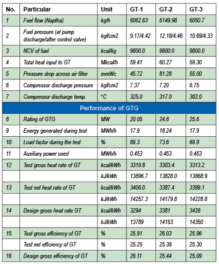
Table 1: Result of the performance test conducted on the GTs…
Energy Efficiency Improvements Identified
The various energy efficiency improvements identified in the GT power plant are described below.
- The exit flue gas temperature in HRSG # 1 &, 2 are 203 & 200°C. It is suggested to introduce CPH for HRSG # 1 & 2 also and bring down flue gas temperature up to 110-115°C. Presently, the heat absorption by DM water in CPH is from 39°C to 56°C only. This additional heat recovery system will lead to reduction of consumption of LP steam in de-aerator. The existing one metre gap between CPH and chimney can also be used to extract more heat from flue gas of all HRSGs. The capital investment may be about ` 2000 lakhs. The expected fuel saving is 10488.2 t / year and the payback period is 5 months.
- Steam injection system is already installed for both the GTs but not being operated now. Since the system is designed for steam injection, no harm is expected and many gas plants are successfully using it. Hence, it is suggested to restore the operation. At full load, about 1.14 t/h of steam can be injected (as per design) and the fuel saving expected is 0.8%. The annual fuel saving envisaged is 734 t.
- The chimney exit contains flue gas (about 357.8 t/h of flow/GT) with 15-16% oxygen and 355-700 ppm of CO. Oxidation catalyst can be used inside HRSG to convert CO to CO2 and the additional heat can be produced and extracted.
- Inlet air cooling system can increase the output of GT up to 10-15% (if cooled up to 15 °C). The rating of present generator is 26.7 MVA. If load power factor is improved to, say 0.95 (from present 0.85), the same generator can take the additional 10-15% load also. Simple air washer unit is a low cost option for cooling the inlet air up to wet bulb temperature so that power generated is increased by about 5% and fuel saving is about 3%.
- On-line compressor wash system needs to be installed and employed on regular basis to reduce the dust load on the compressor blades and to achieve fuel saving.
- Presently, compressed air (about 1,100 Nm3/h / HRSG at 7.4 bar & 35°C) is employed for atomisation of fuel in HRSGs. Since compressed air is highly energy intensive and high grade energy (generated from electrical energy), it is suggested to switch over to steam atomisation (low grade heat energy) to optimise the operating cost.
- The O2 level in flue gas after GT is 13.7-14.1% which may be adequate for the combustion of supplementary fuel in HRSGs. It is suggested to stop the operation of augmentation air fan in HRSG # 2 & 3 and observe for presence of CO content in the flue gas. If there is no CO content, then the operation of augmentation air fan can be discontinued.
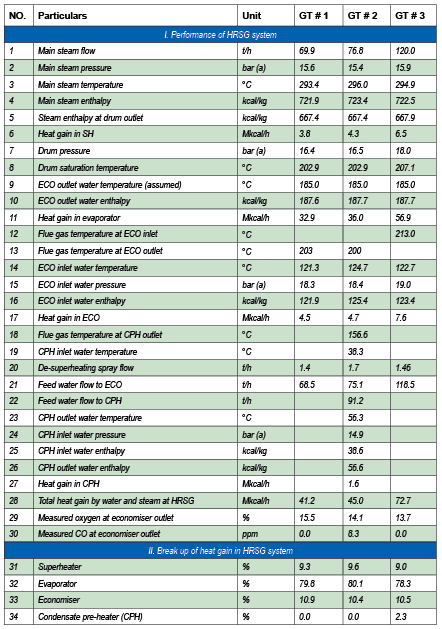
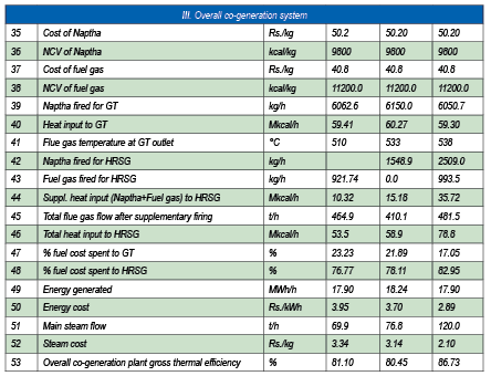
Table 2: Results of performance test conducted on HRSG and overall co-generation system…
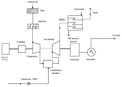
Figure 1: Schematic of the power and steam generation process from gas turbine system…
Conclusions
The main conclusions from the study are as follows:
- Increasing the heat recovery through use of CPH (bringing down the flue gas exit temperature to 115°C) at HRSGs of GT will bring down the fuel consumption.
- Inlet air cooling and online compressor wash system will lead to fuel savings.
- Switching over to steam atomisation in HRSGs will lead to cost reduction.
- The cost of energy and steam generation from co-generation plant is significantly lower than from conventional boilers and TGs.

If you want to share thoughts or feedback on this article, please leave a comment below.


