Existing systems in power grid such as Energy Management System (EMS) and Supervisory Control and Data Acquisition system (SCADA) have the capability to provide only steady state view of power system with high data flow latency. In Supervisory Control and Data Acquisition system (SCADA) it was not possible to measure the phase angles of bus voltages of power system network in real time, due to technical difficulties in synchronising measurements from distant locations.
Measurements were obtained at slower rates; it was not possible to get dynamic behaviour of power system as well as limited situational awareness was conveyed to the operator. Advent of Phasor Measurement Units (PMUs) alleviated this problem by synchronising voltage and current waveforms at widely dispersed locations with respect to global positioning system. PMU is superior to SCADA with respect to speed, performance and reliability.
As per definition of IEEE, PMU is defined as device that produces synchronised phasor, frequency and rate of change of frequency estimates from voltage and/or current signals and time synchronising signal. PMUs provide real time synchronised measurements in power system with better than one microsecond synchronisation accuracy, which is obtained by Global Positioning System (GPS) signals. PMUs are situated in power system substations, and provide measurement of time stamped positive sequence voltages and currents of all monitored buses and feeders. Data from various substations are collected at suitable site, and by aligning time stamps of measurements a coherent picture of the state power system is created. PMUs are time synchronised, high speed measurement units that monitor current and voltage waveforms (sinusoids) in the grid, convert them into a phasor representation through high end computation and securely transmit the same to centralised server.
PMU technology is well suited to track grid dynamics in real time, the data obtained can be used for wide area monitoring, stability monitoring, dynamic system ratings and improvement in state estimation, protection and control. It enables utilities to proactively plan energy delivery and prevent failures.
Fundamentals of PMU’s
PMU technology provides phasor information (both magnitude and phase angle) in real time.
Advantage of referring phase angle to global reference time is helpful in capturing wide area snapshot of power system. Effective utilisation of this technology is useful in mitigating blackouts and learning real time behaviour of power system.
A phasor is a complex number that represents both the magnitude and phase angle of the sine waves found in AC system. The waveform can be represented by:
Where ω is the frequency of the signal in radians per second, and φ is the phase angle in radians. xm is the peak amplitude of the signal. The Root Mean Square (RMS) value of the input signal is (xm /√2).
Positive phase angles are measured in a counter clockwise direction from the real axis. Since the frequency of the sinusoidal is implicit in the phasor definition, it is clear that all phasors which are included in a single phasor diagram must have the same frequency. Phasor representation of the sinusoidal implies that the signal remains stationary at all times, leading to a constant phasor representation. These concepts must be modified when practical phasor measurements are to be carried out when the input signals are not constant, and their frequency may be a variable.
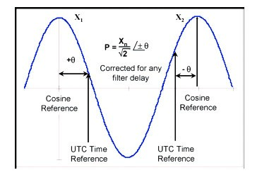
Figure 1: Phasor representation…
Wide Area Measurement Systems
PMU installation is a part of wide area monitoring system network consisting of locating of PMUs throughout the electricity grid at strategic locations in order to cover the entire grid. A Phasor data concentrator at central location collects information from PMUs, and passes that to supervisory control and data acquisition system after time aligning the same.
A complete WAMS network needs rapid data transfer within frequency of sampling of phasor data samples of phasor measurements at PMU are time stamped at each location. GPS installed at PMU location provide accurate time along with time synchronisation among different PMUs. PMU components: The main components of a PMU are data acquisition module, communication module and GPS signal receiver.
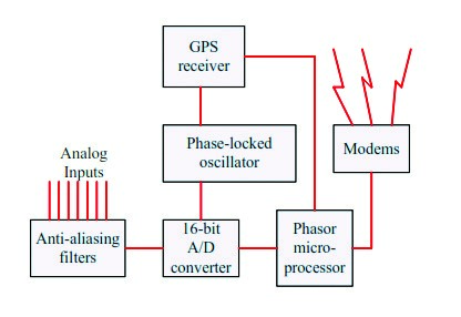
Figure 2: Block diagram representation of PMU…
The analog inputs to device are currents and voltages obtained from the secondary windings of the current and voltage transformers located in substation. All three phase currents and voltages are used so that positive-sequence measurement can be carried out. The current and voltage signals are converted to voltages with appropriate shunts or instrument transformers to match with the requirements of the analog to digital converters.
The sampling rate chosen for the sampling process dictates the frequency response of the anti-aliasing filters. Anti aliasing filters ensure that all the analog signals have the same phase shift and attenuation, thus assuring that the phase angle differences and relative magnitudes of the different signals are unchanged.
The GPS system is used in determining the coordinates of the receiver, although for the PMUs the signal, which is most important is the one pulse per-second. This pulse as received by any receiver on earth is coincident with all other received pulses to within 1 microsecond.
Architecture of Wide Area Measurement Systems
In power grid, the phasor data is used from PMUs placed at different locations. WAMSs are advanced measurement technology to collect information. WAMS perform the function of obtaining data and extracting value from that data.
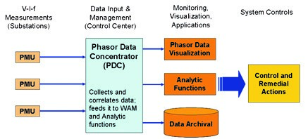
Figure 3: Integration of PMU data…
PMUs are located at substations, and provide measurements of time-stamped positive-sequence voltages and currents of all monitored buses and feeders (as well as frequency and rate of change of frequency). The measurements are stored in local data storage devices, which can be accessed from remote locations for diagnostic purposes.
The local storage capacity is necessarily limited, and the stored data belonging to an interesting power system event must be flagged for permanent storage – so that it is not overwritten when the local storage capacity is exhausted. The phasor data is also available for real time applications in a steady stream as soon as the measurements are made.
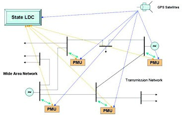
Figure 4 : WAMS architecture…
The devices at next level of the hierarchy are commonly known as Phasor Data Concentrators. Typical function of a PDC is to gather data from several PMUs, reject bad data, align the time-stamps and create a coherent record of simultaneously recorded data from a wider part of the power system.
There are local storage facilities in the PDCs, as well as application functions, which need the PMU data available at the PDC. This can be made available by the PDCs to the local applications in real time.
Motivation for Synchronised Measurements (Synchrophasors)
When a Phasor measurement is time stamped against GPS universal time it is called synchrophasor. This allows measurements taken by PMUs in different locations or by different owners to be synchronised and time aligned, then combined to provide a precise, comprehensive view of an entire region or interconnection. A synchrophasor system is wide deployment of PMUs and dedicated high speed communication to collect and deliver synchronised high speed grid condition data –along with analytics and other advanced online dynamic security assessment and control application. Synchrophasors enable much better indication of grid state, and are used to trigger corrective actions to maintain reliability of the network.
Need of Synchrophasor : – i) To obtain high resolution data ii) The data from different locations are not captured at precisely the same time, iii) Voltage, active power and reactive power normally do not change abruptly, unless there is a large disturbance nearby, iv) System monitoring is crucial during disturbance and transients, v) To capture dynamics of the system faster synchronized data is required.
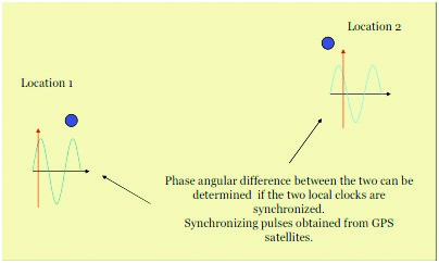
Figure 5 : Synchronization of sample at different locations
Synchrophasors in Indian Power Grid
Indian power grid is one of the largest power grids in the world. Operation of Indian power grid is monitored and co-ordinated through national load dispatch centre and five regional load dispatch centres and state load dispatch centres. To complement visualisation and enhance the situational awareness of large Indian power network to grid operators in control centre synchrophasor projects are deployed. Synchrophasors enable superior indication of grid stress and are often used to trigger corrective actions to maintain reliability.
The first PMU pilot project was set up in northern region in the year 2010, which consists of PMUs along with GPS installed at selected 9 substations in the grid. A Phasor Data Concentrator and other associated equipment are placed at Northern Regional Load Dispatch Centre (NRLDC) located at New Delhi.
Considering the need for wide area measurement for Indian power grid ,installation of PMUs on substations at 400kV level and above in the State & Central grids, all generating stations at 220kV level and above HVDC terminals, important inter-regional connection points, inter-national connection points etc. are being taken up. This will facilitate a Unified Real-time Dynamic State Measurements (URTDSM) towards improved system operation.
PMU application
- Post disturbance analysis
- Stability monitoring
- Thermal overload monitoring
- Power system restoration
- State estimation
- Real time control
- Adaptive protection
All the regional grids in India are interconnected, to assess the power system the angular separations over wide area are one of the key indicators. The larger the phase angle, difference between source and sink, greater is power flow between those points. Greater phase angle differences imply large stress across the interface and large stress could move the grid closer to instability. Angular separation provides insights into the healthiness of synchronous interconnection. Relative phase angles across the system at the starting time of disturbance provide information about initial system loading conditions.It also provides indication of how system reacted to disturbance. In case of oscillations, relative phase angles can be analysed to understand the nature and shape of oscillations – and to know how different parts of system oscillate relative to each other.
Challenges in PMU implementation
- Selecting suitable location for PMU placement
- Integration of synchrophasor technology with SCADA
- Communication delays
- Low frequency oscillation monitoring
- Distorted power system waveforms makes prediction difficult
- High computational requirement
- Developing tools for in depth post facto analysis.
Conclusion
PMU provide innovative solution to traditional utility problems. It also facilitates improved protection and effective control of power system network.