
As it is known, energy is a basic concept in both science and engineering. One complex dynamic system that could be taken is an energy transformer; it can be divided into many subsystems, which are simpler. The nonlinear and active loads are used in many applications, such as motor driver, arc furnace and UPS and so on. These instruments improve the capacity of the control of power energy, but, at the same time, they also produce power pollution. The harmonics and reactive power component of current and unbalance in three-phase system reduce the efficiency of the power system.
Traditionally, the passive filters, composed of resistors, inductors and capacitors, are used to eliminate the harmonics. With the development of power electronics, active power filters are introduced to reduce harmonic current and compensate the reactive component. Commonly, the shunt active power filters are considered as a controllable current source, which is connected in parallel with the mains. The harmonic and reactive component of the load current is drawn by the shunt active filter SAF, so the supply current is sinusoidal with unity power factor, that is, the phases of both supply current and voltage are the same. The control objective is to make the output current of SAF equal to the harmonic and reactive power component of the load current.
The history of Chaos Theory and Poincare Map are discussed here; extensive use of power electronics devices in power system and due to which the system becomes more dynamic. So, the interest in nonlinear oscillations is growing, driven largely by developments in electronics.
Power Quality
The power quality issue is defined as any occurrence manifested in voltage, current, or frequency deviations those results in damage, upset, failure, or disoperation of end-use equipment. Almost all power quality issues are closely related with power electronics in almost every aspect of commercial, domestic, and industrial application.
Harmonics
Harmonic voltages and currents in an electric power system result due to non-linear electric loads. Harmonic frequencies in the distribution power system are a frequent cause of power quality problems.
Harmonics in power systems result in increased heating of the equipment and conductors, missing in variable speed drives, and torque pulsations in motors. Reduction of harmonics is considered desirable.
Description of Chaos
Although there is no a definite definition of chaos, its dynamical properties can be described as follows:
Chaos is an aperiodic, long-term behaviour, in a deterministic system that exhibits sensitive dependence on initial conditions. Aperiodic long-time behaviour means that trajectories in the phase portrait of a system do not settle down towards fixed points, periodic orbits, or quasi-periodic orbits. Deterministic means that the system has no random or noisy inputs or parameters. It has sensitive dependence on initial conditions.
Basic of the p-q Theory
The p-q theory is primarily based on a set of instantaneous calculation of powers in time domain. Voltage and current are sampled instantaneously which means there is no restriction on the shape of their waveform, and it can be applied to three phase with or without a neutral wire. It is based in time domain rather than frequency domain. Thus, it is valid in the steady state and also in the transient state. This shows the theory is very flexible and efficient in designing controllers for active filters and power conditioners based on power electronics devices.
Use of p-q Theory in Shunt Active Filter
The original concept of active filtering was introduced by Strycula and Gyugyi in 1976. Now a shunt active filter can be implemented practically, and many shunt active filters are working all over the world. Their controllers determine in real time the compensating current reference, and source a power converter to synthesize the compensating current reference with high fidelity. Figure 1 illustrates the basic idea behind the shunt current compensation. It shows a source supplying power to a nonlinear load that is being compensated by a shunt active filter. Shunt active filter is actually a shunt compensator. We assume that the shunt active filter behaves as a three phase controlled current source that can generate harmonics in phase opposition depending upon current references Ica, Icb and Icc.
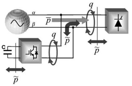
Figure 1: Optimal power flow…
The calculated real power p of the load can be separated into its average (p) and oscillating (~p) parts. Likewise, the load imaginary power q can be separated into its average (q) and oscillating (~q) parts. Then, undesired portions of the real and imaginary powers of the load that should be compensated are selected.
Modelling and Dynamic Analysis of SAF
SAF Introduction:
Static response of passive harmonic filter and other problems have led to a power electronic solution of harmonic distortion i.e. Active Harmonic Filter; a modern solution to old harmonic current problems. Nowadays, passive filters are used to cancel the switching frequency of active filters and high frequencies. Tuned filters are used besides the active filters to cancel specific frequencies and decrease the power of active filters. Active filters have been designed, improved, and commercialized in the past three decades. They are applicable to compensate current-based distortions such as current harmonics, reactive power, and neutral current. They are also used for voltage-based distortions such as voltage harmonics, voltage flickers, voltage sags and swells, and voltage imbalances and load unbalancing and neutral shifting. Moreover, unlike passive filters, they do not cause harmful resonances with the power distribution systems. Consequently, the active harmonic filter’s performances are independent of the power distribution system properties.
The shunt-connected active power filter, with a self-controlled DC bus, has a topology similar to that of a static compensator (STATCOM) used for reactive power compensation in power transmission systems. Shunt active power filters compensate load current harmonics by injecting equal but opposite harmonic compensating current. In this case the shunt active power filter operates as a current source injecting the harmonic components generated by the load but phase-shifted by 1800.
Operation of SAF
The main aim of the Active Harmonic Filter (AHF) is to compensate for the harmonics and reactive power dynamically. The AHF overcomes the drawbacks of passive filters by using the switching mode power converter to perform the harmonic current elimination.
Compensation current signals are fed to hysteresis controller or Pulse Width Modulation (PWM) converter as reference signals to generate gating signals for fast switching Insulated Gate Bipolar Transistor (IGBT) inverter. The inverter generates harmonic currents required by the load through charging and discharging of capacitor. These currents are injected into the system near the load through an interfacing inductor or a coupling transformer. The performance of AHF is independent of system impedance as it compares the injected currents with reference signals and tries to minimize the error.
Figure 2 shows operational waveform generated by SAF; there are three topologies of AHF: i) Series AHF, ii) Shunt AHF and iii) Hybrid AHF. We have selected Shunt AHF (i.e., Shunt Active Filter or Current Active Filter) for this study which is ideal for current harmonic compensation.
A generalize block diagram of SAF is given in Figure (2)
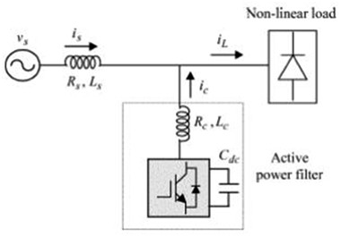
Figure 2: General block diagram of SAF…
Shunt Active filter Controller based on p-q Theory
The Distribution system we considered for research contains 3-phase source, line inductance, nonlinear load and shunt active filter as shown in Figure 3;
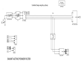
Figure 3: Distribution system SIMULINK diagram…
The SIMULINK diagram of active filter controller based on the p-q Theory is shown in Figure 3. The PWM converter takes synthesizing action on compensating current. The filter control block has the job of performing signal analysis in real time to calculate the instantaneous compensatory reference current signals. Figure 4 shows the most common topology of an active filter for harmonic compensation (maximum compensation) of a specific non-linear load. It consists of a voltage source inverter with a PWM current control (here, hysteresis current control) and an active filter controller that performs an instantaneously working control-algorithm. The shunt active filter controller works in a closed-loop manner, continuously acquiring the samples of the load current and calculating the instantaneous values of the compensating current reference ic for the PWM converter. In an ideal case, the PWM converter may be considered as a linear power amplifier, where the compensating current Ic tracks correctly its reference.
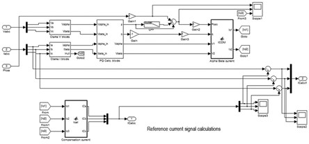
Figure 4: SIMULINK diagram for compensation current calculation…
Simulation results of Shunt Active Filter
For observing the dynamic behaviour SAF we can consider many types of load, like non-linear load, nonlinear plus balance resistive load, nonlinear plus unbalance resistive load, nonlinear load with R-L-C circuit etc. Here we find the result for compensation of nonlinear plus unbalance resistive load. This case is simulated to show the dynamic.
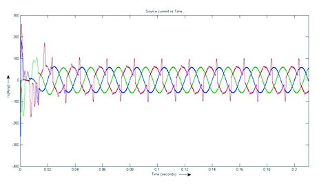
Figure 5: Sinusoidal waveform of source current…
Behaviour of the SAF: The SAF is switched on at 0.4 seconds with the non-linear load only. These switching instants and the dynamic behaviour of the SAF can easily be observed
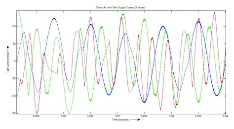
Figure 6: Injected load harmonic current waveform…
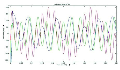
Figure 7: Injected load harmonic current waveform…
Dynamic Analysis of Shunt Active Filter
The SAF system is nonlinear, deterministic, with dimension n = 3. For existence of a chaotic behaviour it becomes necessary to check if it has an aperiodic behaviour and if it presents a sensitive dependence on initial conditions. The result presented in this section is obtained for particular case when the nonlinear load demands the harmonic current;
IL = IP [a sin(!) + b sin(5 !) + c sin(7 !) + d sin(9 !):::]
The phase portrait of the PAF under a p-q theory based control action is depicted in Figure 8. It is not possible to know if there is a point, periodic or chaotic attractor in the phase portrait.
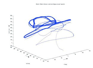
Figure 8: Phase Portrait of SAF…
Conclusion
The p-q Theory based controller has been analysed for power quality improvement. The shunt active filter is implemented for current harmonics of the nonlinear load. It is found from simulation results that p-q theory along with shunt active filter improves power quality of the power system by eliminating harmonics of the nonlinear load.
In later stage analysis of shunt active filter is done. Shunt active filters do not present a chaotic behaviour as long as the corresponding design parameters do not change. However, chaotic behaviour appears when the current harmonic amplitude is varied, particularly, when they become large enough. With the use of Poincare Maps to find out chaotic behaviour of shunt active filter under to different load conditions.
Future Scope
Modelling and dynamic analysis of shunt active filter has been done in this thesis. It shows the chaotic behaviour of SAF (p-q theory based controller is used). The work is to be extended to implementation of Passivity-Based Control via design of passive resistors using the concept of chaos and Poincare Map as discussed in the literature survey. Hence could be used to improve filter performance and power quality of power system. Future scope for this work is the presentation of a procedure for obtaining values for the passivity resistors by which the SAF behaves better.

If you want to share thoughts or feedback on this article, please leave a comment below.


