
But in many plants the problem is not local at all — the incoming 11 kV or 33 kV supply itself is swinging, and every load in the facility sees the same disturbance. Correcting that load by load means buying, installing, and maintaining several machines to fix what is really one problem.
The alternative is to correct the voltage once, upstream, before it reaches the step-down transformer. That is what HT-side regulation does, and for facilities on weak or heavily loaded feeders it is usually the more sensible topology.
Why HT Supply Fluctuates
Feeder voltage in India moves with the load on the network. On long rural and industrial feeders, voltage typically sags during peak hours and rises late at night when demand drops. The swing can be substantial: on feeders we have measured before installations, an
11 kV nominal supply ranging between 8 and 13 kV over a day is not unusual. Seasonal patterns add to this — agricultural pumping loads, for instance, pull rural feeders down for weeks at a time.
A facility connected to such a feeder inherits every one of these movements. The step-down transformer passes the variation straight through to the LT bus, scaled by its ratio.
What Unstable HT Voltage Actually Costs
The damage to downstream equipment — overheating motors, tripping drives, stressed electronics — is well understood, and we covered it in an earlier article on
LT stabilisation. Two costs specific to the HT side get less attention.
The first is transformer derating. A transformer designed for 33 kV input delivers its full nameplate rating only when it receives something close to 33 kV. Fed at a persistently low voltage, its usable capacity can drop to around 70% of nameplate. The facility is paying fixed charges on sanctioned load it cannot actually draw. Holding the input at nominal, within a tight band, restores the full capacity of a transformer the facility already owns — often the single largest benefit of HT regulation, and one that shows up without replacing anything.
The second is maximum demand. Low voltage forces motors to draw more current for the same mechanical output, and that extra current is recorded by the demand meter. Facilities on two-part tariffs pay for it every month. Correcting the voltage typically brings a visible reduction in recorded MDI.
Two Ways to Regulate at HT
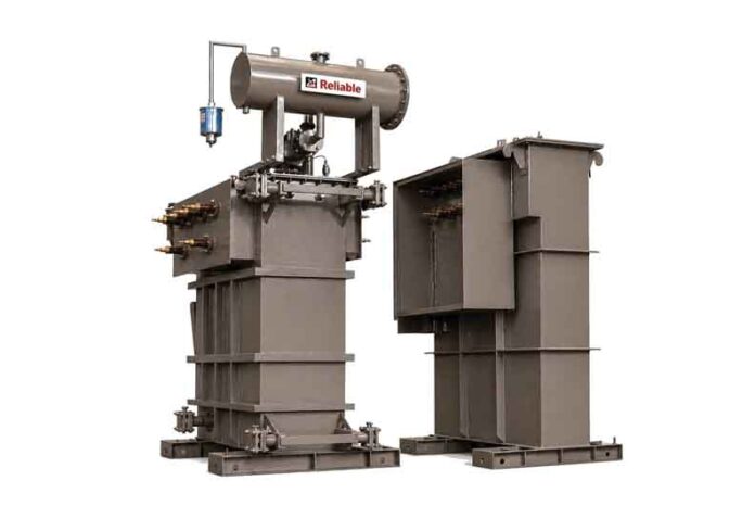
There are two established approaches: a transformer fitted with an On-Load Tap Changer (OLTC), and a dedicated HT automatic voltage regulator based on rolling-contact technology.
An OLTC corrects in steps, typically 1.25% to 2.5% per tap, by physically switching between tappings on the HV winding. It is a proven arrangement and well suited where the correction needed is coarse and infrequent — a seasonal adjustment, or compensation for a known, steady drop. Its limitations appear when the fluctuation is continuous. Each tap change switches current on the HV winding, which produces an arc inside the diverter; frequent operation carbonises the oil and wears the mechanism, and the maintenance that follows needs trained technicians and planned outages. The output also moves in discrete steps, so the voltage is only ever approximately right.
A rolling-contact HT AVR works differently. Carbon rollers travel continuously along a regulating winding, so correction is stepless and the output can be held within ±1% from no load to full load. Because the rollers operate on a low-voltage regulating winding rather than the HV winding, there is no arcing and no oil contamination from switching. The drive motor sits outside the tank, where it can be inspected or replaced without opening anything, and a hand wheel provides manual operation if the motor ever fails. Roller replacement is light work that a site electrician can handle. A practical difference worth knowing: an OLTC transformer must sit at the receiving end of the supply, while an HT AVR can be installed at any convenient point on the feeder.
Neither technology is universally right. If the voltage problem is a fixed offset, an OLTC transformer solves it economically. If the problem is a feeder that moves all day, every day, stepless regulation is the better match — the correction is continuous, precise, and does not consume the life of a switching mechanism.
Specifying an HT AVR
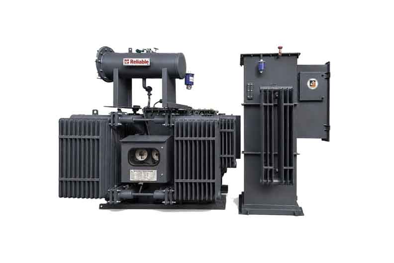
The specification should start with measurement, not assumption. A regulator specified for ±10% on a feeder that actually dips 20% will spend its worst hours against its end stop, which is precisely when the facility needs it most. Units are built for windows matched to the site — asymmetric ranges such as −25% to +9% are common, because Indian feeders sag far more often than they swell.
Beyond the window, the checklist is familiar transformer practice: output accuracy of ±1% across the load range, continuous duty at full load, ONAN cooling with standard protections — Buchholz relay, oil and winding temperature indicators with alarm and trip contacts — and a type-test certificate from an independent laboratory such as CPRI. A twin-tank arrangement, with the regulator in its own tank separate from the transformer, is worth insisting on: it means the moving parts can be serviced without disturbing the transformer itself. HT AVRs are manufactured in India in ratings from 500 kVA to 15 MVA, in 11, 22, and 33 kV classes.
The Combined Option
Where a facility is installing new capacity anyway, the step-down transformer and the regulator do not have to be separate purchases. An HT transformer with built-in AVR integrates both functions into one unit: the incoming supply is regulated and stepped down together, with a single installation, a single oil system to maintain, and less switchyard space than two separate machines. For greenfield sites and substation upgrades this is often the cleaner solution.
What the Investment Returns
The economics of HT regulation rest on four buckets: lower energy consumption, since over-voltage hours waste energy across every load in the plant, with lighting loads showing the largest gains; reduced breakdowns and the repair costs and downtime that go with them; lower recorded maximum demand; and the recovered transformer capacity described earlier. In industrial installations we have supplied, the combination typically pays back the investment within 12 to 18 months. The exact figure depends on how badly the feeder behaves and how many hours the plant runs — which is another reason to measure the feeder first. The measurement that justifies the specification also builds the business case.
For more details: Rohan Sharma, Executive Director, Reliable Power Systems
Email: rpsrohan95@gmail.com, info@reliable.net.in or Website: www.reliable.net.in