

Right from the beginning of the use of electricity by human being (from the day of invention of electricity), need has always been felt for safety switching of the electricity. Switchgears and Circuit Breakers are the final development for such safety operation.
This very essential equipment plays the important role for the immediate disconnection of power supply for any kind of fault occurrence in the system by getting the pulse from the suitable relay or protective scheme in the network.
To avoid heavy flashover/arc during the disconnection, different quenching mediums are generally provided and for quick and fast disconnection, suitable operating mechanisms are used.
Definition of Circuit Breaker:- General definition by the International Electrotechnical Commission (IEC):
“Circuit breakers are mechanical switching devices, capable of making, carrying and breaking currents under normal circuit conditions and also making, carrying for a specified time and breaking currents under specified abnormal circuit conditions such as those of a short circuit.
Classification of Circuit Breakers
According to the type of quenching medium
- Air Break Circuit Breaker ( ABS)
2. Air Blast Circuit Breaker (ABCB)
3. Minimum Oil Circuit Breaker ( MOCB)
4. Bulk Oil Circuit Breaker ( BOCB )
5. Vacuum Circuit Breaker ( VCB )
6. Sulphur Hexafluoride (SF6) Circuit Breaker
According to the operating mechanism
- Pneumatic (compressed air provides the required thrust )
2. Hydraulic (high pressure hydraulic oil of approximately 310 kg/cm2 is used for opening and closing operations
3. Spring (During close, charged spring discharges and simultaneously charges the opening spring)
According to breaking type
- Single break circuit breaker
2. Double break circuit breaker
3. Three break circuit breaker
4. Four break circuit breaker
According to on number of quenching chamber and break
- Single break: One quenching medium per pole with one fixed and one moving contact for breaker operation.
2. Double break: Two quenching mediums per pole with two fixed and two moving contact for breaker operation.
3. Three break: Three quenching mediums per pole with three main and three moving contacts for breaker operation.
4. Four break: Four quenching mediums per pole with four main and four moving contacts for breaker operation.
Based on voltage
- Low- less than 1kV
2. Medium- 1kV to 52kV
3. High/Extra High- 66kV to 765kV
4. Ultra High -above 765kV
Based on application
- Indoor
2. Outdoor
Based on external design
- Dead tank
2. Live tank
Choice of the Breaker
This equipment is the final breaking point for the interruption of power flow in the circuit. So, during this break the electrical parameters like voltage and current on this instrument change – and to avoid the unwanted situation, the following points are to be considered.
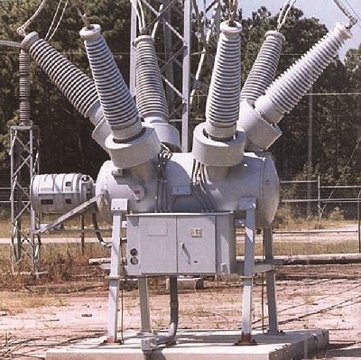
Dead Tank…
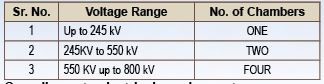
Use of number of interrupting chambers
The voltage dealing across this equipment and break point to limit the spark in the quenching chamber, the use of the chamber is decided – and as per the practice it becomes safe to use one chamber up to voltage class of 245 kV as one chamber and then more as per the increase of the voltage handling situation by this element.
Compliance to electrical requirements
The optimum conditions like Breaking Capacity, TRV (Transient Recovery Voltage), Capacitive and out of phase switching condition are to be complied during choice of the beaker for the circuit.
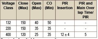
Choice of interruption time
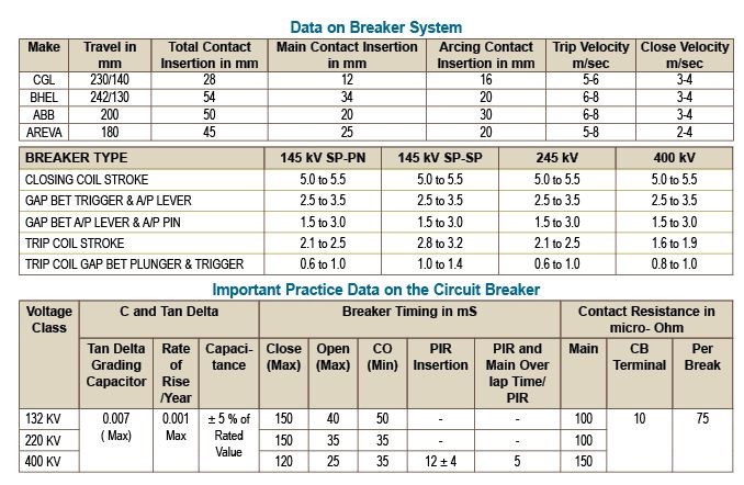
The interruption time is one of the important factors for the protection scheme for the circuit breaker – and becomes critical for the case of higher system voltage application. So, choice of this factor to be considered as per the practice in the following table.
Control of switching over voltage
For condition like unloaded long line, switching of shunt reactors, the transformers loaded with reactors etc. result over voltage in the system. Adding of CLOSING RESISTORS reduces the damping of over voltages.
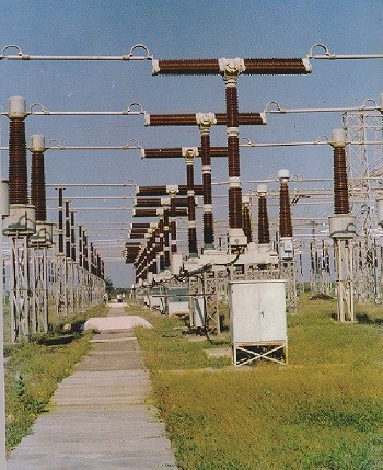
Live Tank…
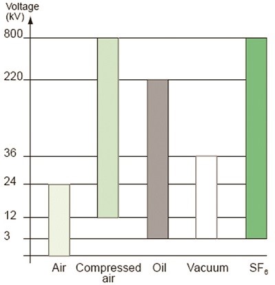
Figure 1…
Mechanical, electrical endurance
The mechanical and electrical endurance limits of Circuit Breakers must confirm to all the relevant electrical standards.
Selection of switching scheme
Calculation of available fault current for Breaker, Main bus continuous current rating selection, Current and potential transformer selection.
Other factors
The other factors like choice of protective relay selection, circuit breaker control power selection, operating mechanism desired, space for installation etc are to be considered for the design of Circuit Breakers
Latest Development in Switch Gears
Considering the different points/factors as described above, different manufacturers regarding Breaker construction have achieved many developments.
The commonly used Circuit Breakers for different rating voltages have been explained below. The graph shown in figure 1 is one of the tentative voltage class practices that could be used for the choice of Circuit Breaker.
Up to voltage range of 36 kV
VCB is one of the best suitable choices of Circuit Breaker up to the voltage range of 36 kV because of its following advantages.
- Rapidly restoring nature of dielectric strength of the gap.
• Short travel stroke at low pressure requires lesser control energy, which in turn results in reduced size and weight of Circuit Breaker.
• Moreover, the operating mechanism for such Circuit Breaker is of (spring-spring) in nature. This mechanism becomes more reliable due to lesser moving parts involved for the operation.
But the only disadvantage in the use of VCBs is the precaution in maintenance of Vacuum during its operation. However, this Circuit Breaker has gained maximum popularity for 36 kV range.
Voltage range of 72 kV up to 800 kV
For higher voltage range, SF6 gas is used as the arc-quenching medium in a hermetically sealed chamber. SF6 gas is being extensively used now-a-days, due to its inherent property of immunity to the climatic and environmental condition.
Advantages of SF6 gas
- Colourless, odourless non-flammable, non-toxic / biologically inert
• High dielectric strength (RRRV 2.5 x air)
• High arc interruption capability (10 x air)
• High heat transfer characteristics (2 x air)
• Insulating properties remain un-altered as carbon is absent in the molecules
• Remains without condensation up to -30 degree temperature
• Density is 6 times as of air
• Chemically stable / non-corrosive
• easy to handle
• Electronegative in nature.
Function of SF6 during puffing
During breaker operation, the contact movement creates the puffer action, which momentarily increases the dielectric strength and arc extinguishing properties of SF6 gas. During contact opening, the puffer action forces a pressurised stream in the form of axial jet (in whirlpool formation) of SF6 gas through contact area, cooling and extinguishing the arc at current zero. The action moves a large volume of SF6 gas through the arc zone to absorb heat – and the free electrons from the plasma quickly reduce arc energy. Puffer action means minimum contact erosion and longer contacts life.
Concepts on Circuit Breakers
Graphic representation of switching action of breaker
Graphic representation of current interruption
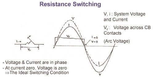
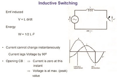
While switching the circuit, the electrical elements that come across the system are of three types (Resistive, Inductive and Capacitive). This paragraph describes the flow of current and its wave form analysis for the voltage application to the load. Basically, for resistive, the current becomes in phase to the application of voltage – and lags to the voltage for inductive load and leads to the voltage for capacitive load. The detail circuit and explanation is given below for circuit reference.
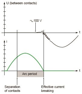
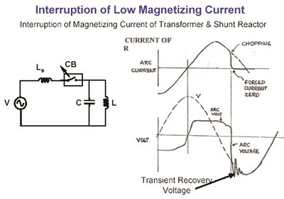
Graphic representation of current interruption in circuit breaker
The current interruption flow and its behaviour can be shown in the graphic representation form as shown below.
Graphic representation of switching action
Graphic representation of current interruption
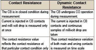
Notes on contact resistance
100 A DC current passed through main contacts & voltage across the terminals of the circuit breaker is measured. The contact resistance is calculated by V= IR formula.
The acceptance limit for contact resistance is 1.2* Ru, where Ru is the contact resistance measured during temperature rise test.
Notes on DCRM (Dynamic Contact Resistance Measurement)
The Normal Resistance Measurement is done as the ratio of voltage applied across the main contact to the current passes through it. But during breaker operation, the arc resistance plays the important role to monitor the status of the main and arcing contact – and calculated in the form of DCRM. So, Dynamic Contact Resistance Measurement is a signature of change in contact resistance of CB during operation. It plots the variation in contact resistance while first the main, then the arcing contacts engage and disengage during CO operation.
Req = R*r/(R+r) = r/(1+r/R),
r = Main contact, R = Arcing contacts
Comparison on concepts of contact resistance and dynamic contact resistance
Notes on dew point measurement
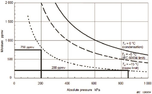
In general, the dew point of SF6 is defined as the temperature at which the gas in the breaker starts condensing. The measurement of this point is done either at the atmospheric pressure or at the rated pressure. Dew point when measured keeping regulating valve in service at the outlet of dew point kit to allow required flow rate of gas/air, it is called dew point at rated pressure of CB and when measured by regulating the gas flow at the inlet of dew point kit and keeping outlet regulating valve in fully open condition, then it is called dew point at atmospheric pressure.
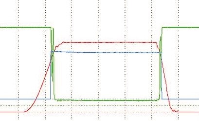
Typical DCRM graph for healthy pole…
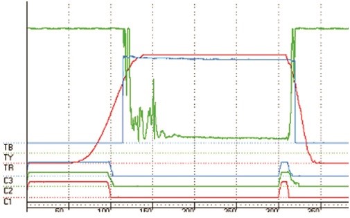
Typical DCRM graph for suspected pole…
Notes on moisture effect to SF6 gas
When arc results during breaker operation, SF6 gas decomposes due to the chemical reaction with the eroded particles. If the moisture remains due to leakage, the chemical reaction also causes the degradation of insulation and corrosion in the interrupting chamber. So, the trace of objectionable moisture is to be done. Dew point measurement helps in monitoring this trace in the SF6 chamber.
List of routine tests conducted on circuit breakers
- Mechanical operation tests
• Electrical sequence test ( control & auxiliary circuit check)
• Measurement of speed & time (no load operating characteristics)
• CRM
• DCRM test and Analysis
• Milli volt drop test (contact resistance measurement )
• High voltage test on main circuit
• High voltage test on control & auxiliary circuit
• Gas leakage tests
• Gas density switch operation tests
• Measurement of tripping & closing coil resistance
• Voltage withstand test on control circuit
• Power frequency withstand test on main circuit
• High pressure test on hydraulic mechanism
• Pump charging time for operations
• Leak testing hydraulic mechanism
• N2 leak test on accumulator
• Replenishing time measurement for compressed air
• Air pressure switches operation
• Safety valve operation
• Air leakage test
• Operational Analysis
• C & Tan Delta of grading capacitors
Type tests
- High power tests
i. Direct tests
ii. Synthetic tests
– Short circuit tests
– Switching performance tests
• High voltage tests
• Mechanical and environmental tests
• Temperature rise test
Notes on Condition Monitoring
Health monitoring of the circuit Breaker can be done in various methods either ON- Line or OFF-line practices.
On line condition monitoring techniques
- SF6 gas pressure monitoring
2. Trip coil supervision
3. Auxiliary contacts operating timings
4. Contact speed measurement by installing transducers
5. Line current and cumulative fault current using external ct- under evaluation
OFF line condition assessment techniques
- Operating timings of main and auxiliary contacts
2. Trip/close coil currents measurement
3. Static contact resistance measurement-
4. Vibration measurement under evaluation stage
5. Contact travel measurement
6. Dew point measurement of SF6 gas
7. Dynamic contact resistance measurement
8. Tan delta measurement of grading capacitors.

If you want to share thoughts or feedback then please leave a comment below.


Nice to become browsing your blog once more, it has been months for me. Properly this write-up that ive been waited for so lengthy. I want this write-up to total my assignment within the college, and it has exact same topic with your article. Thanks, excellent share.
Not many can comprehend these types of ideas, fortunate I consider the author one of them.