
Importance of Line Differential Protection
Protection philosophy of high-voltage transmission lines traditionally calls for distance protection relays, which are basically impedance operated relays. Distance relays and their time of operations are dependent on voltage, Source-Impedance-Ratios and length of line. For short lines, or lines connecting power-plant to industry like in the case of Hindalco, Line Current Differential relays are deemed crucial, owing to their independence from loss or absence of voltage or SIR, and their faster operation times. There are a total of 10 numbers 132kV transmission lines of which 6 are double circuit and 4 nos. are multi-circuit (4 Circuits on same tower) between Hindalco CPP at Renusagar and Hindalco Smelter Plant at Renukoot. Because of strong zero sequence coupling between the parallel circuits, distance protection tends to over-reach or under-reach, even after including compensation factor. This was specially observed during lightning faults, thereby propagating the disturbance further. Additionally there were 3 short lines only protected by conventional relays. Numerical Line differential relays can also have back-up distance protection, to work in tandem with an alternate distance protection relay on the line. Figure 1 below shows a typical line current differential-cum-distance backup protection using Schweitzer Engineering Laboratories make SEL 311L relays, applied to a line having two-terminals.
Challenge involved with the Line Differential application at Hindalco
There a total of 10 numbers 132kV transmission lines between Hindalco CPP at Renusagar and Hindalco Smelter Plant at Renukoot. Each of these lines were protected with separate distance relays with Power Line Carrier Communication, linking both ends of the line. Single-mode Optical Ground-wire laid over transmission line exists between the two stations of approximate length 35kilometers. The remarkable factors for line differential protection of some of these lines (Implemented in 6 lines) were as follows:-
- Non-identical CT ratios at each end of line
• Non-identical CT Class at each end of line(Class PS at one end, Class 5Px at other end)
• A Relay operation time of 17-22 ms in Test Bed as well as in Actual operation, was recorded by HIL independent DFR.
![]()
Figure 1: Typical Line Differential Relays on a transmission line
The line differential relays were required to operate correctly with existing system parameters and remain immune to external faults. The challenges owing to the above factors were prominent during external faults when CTs at one end of a line saturate, whereas the CTs at the other end did not. False differential currents arise during such conditions, which may cause the line differential relays to operate incorrectly. Since, such faults are external to the line, the line differential relays were required to remain stable during such disturbances. Figure 2 below shows one such case where CTs at only end were found to be saturated.
Line Differential solution with Backup Distance element provided by SEL
SEL 311L line differential relays employ the Alpha Plane Differential principle and provide the advantage of restraining differential operation for such through fault conditions where only one set of CTs has saturated on a line. SEL conducted simulated tests with the disturbance records received from Hindalco and based on the reports by SEL, one pair of SEL 311L relays were installed as a trial installation on 132kV Line #8 having CT Ratio 2000/1A, Class PS at Renukoot End and 1200/1A, Class 5P20 at Renusagar End. The simulated test waveform and the results plotted on the restraining region on alpha plane graph of the SEL 311L, for the above disturbance is shown in Figure 3.
The application architecture was as shown in Figure 1 earlier. The line differential element is dependent on the communication channel between the two stations. The SEL 311L relays monitor the communication channel status and were configured such that distance protection element takes over as the primary protection, to compensate for communication channel fail conditions. In case of communication channel being restored line differential element is automatically restored, again as the primary protection element.
Theory of the Generalized Alpha Plane Differential in the SEL 311L
Traditional current differential relays use a percentage bias-restraint characteristic. SEL introduced the concept of a digital 87L principle that used a restraint characteristic implemented on the Alpha Plane. The α-plane is a current-ratio plane, illustrated in Figure 4 below. The ratio of the remote terminal current to local current is plotted on the α-plane. Ratios that lie within the restraint region prevent the differential element from operating. This characteristic responds well, to phase alignment errors by explicitly looking at the angle difference between the local and remote currents. Sensitivity is controlled, by a separate comparison of operate current versus a minimum sensitivity setting and further enhanced by the presence of zero-sequence and negative-sequence elements, in addition to segregated phase elements.
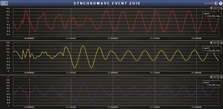
Figure 2: Disturbance record showing saturated waveform collected from only at one end of the line
The generalized α-plane develops two equivalent currents, IL(EQ) and IR(EQ), that produce the same operate and restraint as any number of original terminal current phasors. The ratio of smaller current to larger current is always plotted; thus, the ratio on the generalized α-plane always has a magnitude of one or less. Because the α-plane is symmetrical, all ratios are reflected to positive angles in the first and second quadrant. IL(EQ) and IR(EQ) themselves are composite signals, made up of operate and restraint values, as shown in below equation. To accommodate CTs with different nominal ratings, the generalized α-plane relay automatically calculates taps and performs difference calculations in per unit. The generalized α-plane relay also employs an external fault detector that uses raw samples to determine if a fault is external to the zone of protection within one-quarter of a cycle. Once an external fault is detected, the relay switches automatically from normal to more secure settings, improving security in case a CT saturates during the external fault. The plot on the complex plane, is obtained by calculating the fundamental phasor values of currents IL and IR, using the output signals of the 16 samples-per-cycle cosine filters and then determining the phasor IR / IL ratio. Further, for data alignment, a traditional ping – pong method is used for symmetrical channels.
Industry Unique Three-terminal Application at Hindalco
Hindalco has a 132kV Line between Co-generation Switchyard and Rectifier Plant 2, with a tapping which connects the Extrusion Press, as shown in Figure 5. Lengths of all the three lines are very short(less than 5Kms), which makes Line Current Differential the ideal choice for Line Protection. The communication channel is conventional Fiber Optic cable between each of these terminals. For an internal fault on the line, fault feeding may happen from either of Co-generation End and/or Rectifier Plant 2 End. Three-terminal lines with sources at more than one end are always challenging to protect. Dual communication channels connect each of the three-ends, for these kind of applications. In a three-terminal application, the α-plane is plotted by vector-addition of the two-remote end currents, to determine IR, the local current is noted as IL and the phasor ratio of IR / IL is derived. Simply put, the SEL 311L converts the three-terminal line to its electrically equivalent two-terminal line and runs the two-terminal protection algorithm.
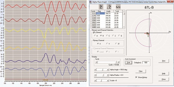
Figure 3: Simulation test run in lab tests with combined COMTRADE records from both ends and the results in Alpha Plane Graph of SEL 311L showing the fault plotting in restraining region
For internal faults with outflow, external faults with CT saturation, and terminal(s) with open breaker or low current, all three alpha calculations do not make the same trip/restrain decision. During such events, the relay executes special CT Saturation Security Logic to provide both security and dependability to the differential elements. This logic differentiates between an internal and an external fault. If the traditional restraint region is not enabled, the CT Saturation Security Logic sets the restraint region angle at 180 degrees. The CT Saturation Security Logic is only enabled when the relay is used in a three-terminal application.
This application is also designed with two-setting groups. Line differential is primary protection in Group 1 with backup directional over-current and earth-fault elements, having separate inverse and definite-time delays. Group 2 is enabled for a communication fail condition and backup directional elements take-over as the primary protection. The first group is have higher time delays and the second group has lesser time delays.
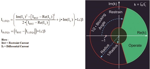
Figure 4: Concept of the Generalized Alpha Plane
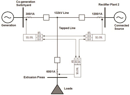
Figure 5: System Configuration for the three-terminal line at Hindalco
For naming convention, we consider Co-generation Switchyard as Station S, Rectifier Plant 2 as Station L and Extrusion Press as Station R. The SEL-311L uses all three possible combinations of remote current to process all 87L elements, as shown in Table 1.
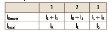
Table 1: Three Possible combinations of Remote and Local Currents at each of the three terminals
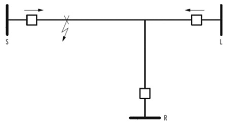
Figure 6: Study of an internal fault on the line, with fault-feeding from the Co-generation End.
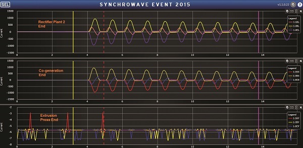
Figure 7: Disturbance Record showing a B-G fault record showing currents at each of the three terminals
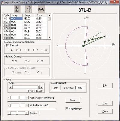
Figure 8: Alpha Plane plot of the B-G fault seen in Figure 7
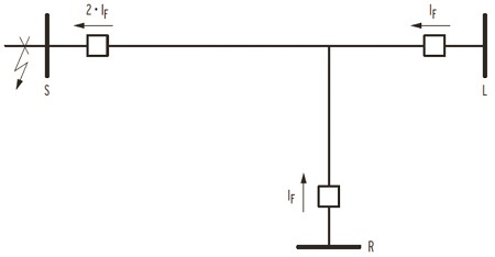
Figure 9: An external fault on the three-terminal line
Analysing faults on the three-terminal line
To help further understanding of the application, we have analysed performance with actual faults and explained with actual disturbance records. Considering a single-phase to ground (B-G) fault on the main line, we have observed fault feeding from Co-generation End and Rectifier Plant 2 End, as seen in Figure 6. The disturbance record capture from Rectifier Plant 2 End shows the details of fault currents from all three-sides in Figure 7 and the α-plane plot in Figure 8. All three relays process the 87LG elements, using three possible combinations of remote ground current, from Table 1. The scheme then selects the trip/restrain decision produced by the processing method that used the largest ground current as the local current.
In effect, the relay with the largest local current makes the proper trip/restrain decision, and the other two relays make the same trip/restrain decision as the relay with the largest local current. The same processing occurs in all three relays. This method works in all cases where the out feed current is the smallest terminal current.
Continuing with the algorithms explained earlier, the fault contribution from the remote ends, vector additions and α-plane plotting , the scheme brings the security of the α-plane and calculation of differential quantities at each end, to provide stability against CT saturation or external fault conditions. An example of a through fault is shown in Figure 9.
Conclusion
Current-only differential schemes must balance security challenges from CT saturation and channel asymmetry with sensitivity: the more secure the scheme, the less fault coverage. When we consider the cumulative errors of CT saturation and channel asymmetry, the α-plane element provides better sensitivity and security, as compared to percentage differential relays using a slope setting. The α-plane element is very tolerant of CT saturation while maintaining a maximum degree of fault resistance coverage. Restricting phase differential elements to detecting three-phase faults, while using a negative-sequence differential element to detect all other fault types, maximises sensitivity while maintaining security. The α-plane analysis helps to visualise how various power system and protection system phenomena affect unit-type protective relay element security, dependability, and sensitivity.

If you want to share thoughts or feedback then please leave a comment below.


