

Unobstructed sunlight throughout the day can add to generation capacity to mitigate power crisis through Photovoltaic (PV) system. India has high solar insolation, hence it has high potential of utilising solar power. Jawaharlal Nehru National Solar Mission (JNNSM) has targeted to add a capacity of 20,000 MW by 2022. A grid-connected PV system feeds to the grid. But when sun is unavailable or solar insolation is insufficient to generate power, it draws power from grid. Grid interconnection raises various issues out of which significant ones are interconnection voltage level, feeder reliability, protection and power quality issues. Central Electricity Authority (CEA) has formulated regulations regarding technical standards of connectivity to grid.
PV panel produces DC power. It may be fixed or tracking the sun to extract maximum power [3-4]. In a grid- tied system, AC power from inverter is fed to grid after synchronisation. Generally systems below 100 kW are connected to 400 V at low voltage distribution line, where as beyond this up to 3 MW at 11 KV and 5 MW and above at 33 KV. Evacuation of power demands reliability of distribution system to be 99.5 %. So, power systems with low penetration of distributed generation demands:
- Ensure that the generation unit operates safely
• Ensure that the grid is not disturbed
Protective relaying is concerned with the redundancy and reliability of the system. The multi-function relays provide a high level of protection at a very attractive cost. The multi-function digital relay can protect a generator from voltage, frequency, reverse power, over current, loss-of-field, and over-excitation (V/Hz) disturbances, while also providing breaker failure/flashover protection. If a multi-function relay is out of service, the consequences can be more severe since many protective functions may be incorporated into the unit. So, a second multi-function digital relay could provide voltage, frequency, over current, directional power, and directional over-current protection as a backup.
PV Generation Protection
Due to cost as well as space of individual relay, systems designed in the past had reduced level of protection. With the use of multi-function digital relays, less no of relays reduce panel space, wiring and other costs. Therefore, a very high level of protection becomes affordable; however the reliability issue demands back up for important functions.
With the advent of multi-function relays, the trade-off of protection coverage versus cost has taken a marked turn toward more protection. In order to put the PV generator protection problem in perspective, a short discussion on protection schemes is discussed herewith. The “IEEE Guide for AC Generator Protection” ANSI C37.102 is one of the premier documents available to the protection engineer for guidance in generator protection system design.
A sample one-line protection scheme for the first commissioned PV generator located at Sadeipali, Bolangir, Odisha with capacity of 1 MW is shown in Figure 1. The PV module delivers AC power at 270V after inverter which is stepped up to 11 KV by transformer. In this paper, discussions are limited to faults or abnormal conditions that are primarily related to grid- interconnection of such PV system at 11 KV level. The generation started in June 2011 and initially fed to a 11 KV rural feeder. OERC has fixed Rs.15/KWh for first 15 years and Rs 7.5/KWh for 13th to 25 years. As the feeder was supplied from 33/11 KV Laltikra as well as 1 MW PV system installed by Rajratan Energy Holdings Pvt. Limited(REHPL), effective protection system became important. As in single line diagram (SLD), the PV system has two bays. It has Line-In-Line-Out (LILO) arrangement for 11 KV Chandanvati Feeder. The connected load of 11 KV feeder is more that 1 MW. The PV generation is metered and fed to this feeder at an intermediate location of Sadeipali. During night when there is no generation of PV it is bypassed and after off-grid closing I-5 shifts the total load of the feeder to grid. The station auxiliary supply of PV power plant is also drawn from grid. The main fault types and disturbance conditions are classified as:
- Phase Faults
• Ground Faults
• Abnormal voltage
• Unbalanced Currents
• Abnormal Frequencies
• Breaker Failures
• System Faults
In addition to the above faults and disturbance conditions, loss of synchronism is also protected. This paper is focussed on important points in grid interconnection protection.
The numbers used in Figure 1 represent a shorthand notation defined by the ANSI/IEEE Standard C37.2-1979 to identify specific relaying functions. The guide to the use of these numbers and their definitions is found in reference. The protection system falls under two categories discussed below: Primary Protection and Secondary Protection.
The primary protection trips the appropriate breakers to clear faults in the protected zone only. The primary protection is typically the fastest protective function for detecting the designated fault type.
The backup protection operates independently of the primary protective function only if the primary protection fails or is temporarily out of service. It may be slower to operate than the primary protection so that the primary protection has the first chance to operate.
Phase Fault Protection of Feeder
Phase faults in a incoming feeder can be detected and protected by a pack of 3 nos Over Current relay (50) and 1 no IDMT earth fault relay (51N). One IDMT non-directional over current relay (51) is also provided.
Phase Fault Protection of Transformer
Phase faults in a transformer stator winding can cause thermal damage to insulation, windings and the core. Primary protection for transformer phase-to-phase faults is best provided by a differential relay (87T) used for unit protection. Differential relaying will detect phase-to-phase faults, three-phase faults, and double-phase-to-ground faults.

Figure 1: Single line diagram of first 1 MW PV power plant at Sadeipali, Bolangir, Odisha evacuating power at 11 KV
Ground-Fault Protection
One of the main causes of ground faults is insulation failure. Depending on the location of the fault, separate ground-fault protection is usually provided by instantaneous over current relay (50N).
Backup protection for ground faults can be provided by an Inverse Definite Time Over-current relay (device 51N) in conjunction with an Instantaneous Over current relay (device 50N) applied at the generator neutral to detect zero sequence unbalance current which flows during ground faults.
Abnormal Voltage Protection
Overvoltage may occur during a load rejection. The overvoltage relay (59) is used to protect the PV generator from this condition. Three limits can be set which are in the range of 110-135% with time range 0.05 to 2 sec. Similarly, under voltage may occur due to sudden reactive power demand which can be taken care of by under voltage relay (27). Under voltage range is 50-90%.
Abnormal Frequency Protection
Frequency variation in the grid requires a response from the PV system for safety of the equipments at point of common coupling (PCC). The PV system should operate in synchronism with the grid with ±1% and for exceeding range must trip with in 0.2 sec. Again on restoration of frequency with in this range needs resynchronisation.
Over Frequency Protection
The multifunction relays provide a two-set point over frequency relay (81O) that can be set to alarm or trip on an over frequency condition.
Under Frequency Protection
Overloading of a generator, perhaps due to loss of system generation and insufficient load shedding, can lead to prolonged operation of the generator at reduced frequencies. While load-shedding is the primary protection against generator overloading, under frequency relays (81U) should be used to provide additional protection. In addition to relays fuses are provided and fuse failure is also protected by fuse failure protection (97).
Breaker Failure Protection
Backup protection must be provided for the case where a breaker fails to operate when required to trip. This protection consists of a current detector, in conjunction with a timer initiated by any of the protective relays in the generator zone. The breaker failure relay (95) in association with trip coil supervision will initiate tripping of the backup breakers.
Anti-Islanding Control and Protection
In Grid-tied mode of operation, when the output power of the inverter matches with the total load on the grid, the failure of grid does not create any change in voltage or frequency. The inverter continues to support the load. This condition is not safe. It is mandatory for power exporting inverters to detect grid failure and stop exporting power to the grid within 2 seconds.
System Fault Backup
Phase Faults
The voltage-restrained/controlled over current function (51V) can also be used for this backup function. The voltage-restrained/controlled over current relay will restrain operation under emergency overload conditions and still provide adequate sensitivity for fault detection.
Ground Faults
Backup for system ground faults can be accomplished with a time over current (51) relay connected in the neutral of the step-up transformer primary.
A master trip relay (86) connects to all the relays and connects to the tripping devices such that its command is used for tripping the Circuit Breaker.
The inverter switches automatically to off-grid in case of grid failure. But if it fails to do so, to prevent accident due to back feeding of power manual Air break (AB) switches are provided.
Earthing inside the yard is also important for safe operation of operators. The next section discusses the actual relays used in the case studied and importance of power quality requirements.
A protection philosophy should cover the various fault types.
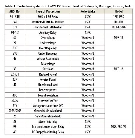
Table 1 contains a functional list for the important relays used including two multifunction protection relays that are used in the installed PV system.
The important functions have been discussed in earlier section. The relays incorporate six or ten protective functions in one package.
Power Quality Requirements
Harmonics on AC side
- Harmonic distortion is caused principally by non-linear load such as rectifiers and arc furnaces and can affect the operation of a supply system and can cause overloading of equipments such as capacitors, or even resonance with the system leading to overstressing (excessive voltage & current). Other effects are interference with telephone circuits, metering errors, overheating of rotating machines due to increased iron losses (eddy current effects), overheating of delta connected winding of transformer due to excessive third harmonics or excessive exciting current.
ii. The limits for harmonics shall be as stipulated in the CEA Regulations on grid connectivity which are as follows:
a. Total Voltage harmonic Distortion = 5%
b. Individual Voltage harmonics Distortion = 3%
c. Total Current harmonic Distortion = 8%
Voltage Unbalance
The Voltage Unbalance at 33 kV and above shall not exceed 3.0%.
Voltage Fluctuations
- The permissible limit of voltage fluctuation that may occur repetitively is 1.5%.
ii. For occasional fluctuations the maximum permissible limits is 3%.
DC Injection into the grid
Improper design of inverter may cause DC injection into the grid. It causes saturation of transformer; reduce its efficiency and life. It is proposed by BIS to limit DC injection within 1% of the rated current of the inverter as per IEC 61727. The power conditioning unit (PCU) takes care of the following limits of power quality requirement.
Conclusion
In this paper a detailed case study of protection system of a PV power plant has been presented. The function and the ANSI codes for different relays have been given. The primary and back up protection system have been discussed for a LILO arrangement. The multifunctional relays used with their advantages have been discussed. But it can be seen that with such interconnection at distribution level successful utilisation of capacity is possible only when reliability of feeder is high and synchronisation is maintained. Further, there is requirement of manual operation after sun set to bypass it. However, with such an arrangement, the consumers at tail end of the feeder will have quality of power better than with only supply from grid.

If you want to share thoughts or feedback then please leave a comment below.


