

Commissioning tests and periodic on-site maintenance checks are essential for the safe and outage-free operation of power transformers and substations. A combination of routine electric tests and advanced diagnostic techniques in accordance with the IEC 60060-3, IEC 60076, IEEE Std. C57.12.00, IEEE Std. C57.152 – 2013, and GOST 11677-85 standards can be performed with a dedicated test system. These tests are also valuable in troubleshooting in case of an outage. Deterioration of electrical insulation can be identified with the high voltage insulation tests (insulation resistance, dissipation factor and capacitance measurement, dielectric frequency response). Mechanical damage due to the transport or the effect of faults, malfunctions and winding shorts are typically found using frequency response analysis, winding resistance measurement and onload tap changer tests. Confirmation of ratio, vector group, no-load and short-circuit losses is desirable after repairs to ensure that these have been carried out to a high standard. Oil samples are routinely taken for breakdown tests and gas analysis.
![]()
Performing all these tests on-site requires many different devices, each with its own test leads. Often such testing is time consuming and tricky because of the numerous test arrangements that have to be set up, and the need to climb repeatedly to the top of the transformer to change connections. The latter can easily lead to accidents during testing. A test van can easily accommodate all of the abovementioned methods and instruments, and organize them to provide an automated test flow. This article discusses a test van solution with centralized control and reporting software and a single connection to the test object, which is shared among instruments. Automated test circuit arrangement and switching processes to enable safe test flow are also provided.
Upon completion of each measurement, results are automatically transferred into the test protocol. Database software allows calculation of the differences between measured values as well as comparison of measurement results with the nameplate and previous data. At the heart of the system is a switch box that provides automated (software-driven) selection of HV and LV methods and test schemes. This article describes test methods and report structures to show how testing time is reduced and human error avoided.

Measurement techniques provided
Four instruments are integrated into the core of the system:
- Insulation tester (5 kV megohmmeter)
2. Capacitance and tan delta test set (exciting current)
3. Winding resistance
4. Turns ratio meters.
The test equipment is mounted in the rack as shown in Fig.1.
Cable drums of 30m length are located in the back of the vehicle. If this length is not enough, the instruments can be removed from the drawers and used standalone with standard test leads.
Optional further test capabilities can be added:
- Short circuit impedance
- Power loss for no-load and short circuit conditions
- Frequency response analysis
- Moisture assessment with the DFR technique
- Single-phase HV source up to 100 kV AC and 70 kV DC for withstand tests
- Oil breakdown test set.


Insulation testing
There is a need for preventative testing on transformers taken out of service. Most commonly, measurements of the insulation parameters of transformers and bushings are made with a megohmmeter and a dissipation factor (tan delta) test set. The results provide defined values for the insulation condition, which can indicate the presence of major defects, and in some cases, locate the defect origin. To measure the insulation resistance of power transformers a DC voltage of several kilovolts is used. Capacitance and dissipation factor measurements for winding insulation are conducted with an AC voltage up to 10 kV using circuit arrangements similar to those used for the DC insulation resistance measurements. This means that an HV switch can be used for commutating the test leads between the megohmmeter and the dissipation factor test set, as shown in Figure 2.
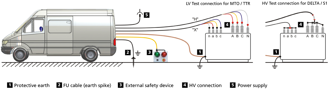
The user interface provided by the auxiliary software that controls the switch box is shown in Fig.3. The user works with two sets of test leads (for HV and LV testing). When the test leads have been connected to the test object as shown in Fig. 8, an instrument can be selected (powered on). The instrument is then controlled by a dedicated software package to perform tests, collect results and manage them within a database as shown in Fig.4.


Ratio testing and vector group verification for three-phase transformers
Transformer turns ratio tester and a transformer ohmmeter is deployed. Both devices share the same multi-core leads, so it is practical to develop an LV switch that allows the switching of test leads between these two instruments, as shown in Figures 5 and 6. The test leads (one multicore cable for the HV side and another for the LV side) are 30m long. Each has four Kelvin clamps with separate current and potential contacts.
This arrangement means that measurements are made with a four-wire circuit that compensates for lead length. Depending on the standards specified, the ratio measured during commissioning should not differ by more than 0.5% between windings or from the nameplate value. Simultaneously with the ratio testing, the instrument determines the vector group of winding interconnection in three-phase power transformers.

Winding resistance measurement
Winding resistance measurements should be performed for all tap positions.
Simultaneous connection to the HV and LV terminals allows the use of the dual-magnetization method. This is especially valuable with large transformers that have a delta connected LV side. The advantages of the dual magnetization method are shown in Figure 7. The core of the transformer is magnetized by the “effective flux”, which is 10 times higher than the flux developed during a single LV side measurement. Typical test currents are between 0.1% and 5% of the rated winding current. Currents more than 10% of the rated value may cause heating, which could compromise accuracy. For comparison purposes, temperature correction can be performed using the formulas for copper and aluminium built into the software. For field tests, the values of the winding resistances in a three-phase transformer measured at the same taps and temperature should not differ by more than 1%between phases. Absolute readings after temperature correction should be within 5% of the values provided by the manufacturer. After finishing winding resistance testing, it is recommended to perform core demagnetization (or removal of remaining magnetization). The best transformer ohmmeters provide facilities for doing this.
Before measuring no-load losses or carrying out frequency response analysis on a transformer taken out of service, the core must be demagnetized to eliminate magnetization that may have been caused by interrupting the current at other than a zero transition. Demagnetization is accomplished by injecting into one of the HV windings a cyclic DC current flow of changing polarity with amplitude decreasing from maximum to zero, as shown in Figure 9.


Power loss measurement
No-load losses
No-load loss measurements are usually done during commissioning and after repairs on service aged transformers in order to identify an inter-turn shorts, core sheet shorts and core-ground faults. It is recommended that the no-load test is carried out at 380/220 V. The test voltage is applied to an LV winding, with the other windings left open. It is preferable to excite windings with phase-to-phase voltage of 380 V. This is because a phase-to-ground voltage could be subject to harmonics and would not be perfect sine curve, which could lead to inaccuracies in the results. It is acceptable to measure no-load losses at frequencies close to the rated value of 50 Hz (±) 3%. For aged transformers no-load losses are not specified in the standards, so when measuring at a frequency outside ±3% tolerance band there is no need to make corrections. For three-phase transformers the no-load loss is measured phase-by-phase. This allows the losses for the phases to be compared to reveal a faulty phase, and also allows the results to be compared with data provided by the manufacturer.
Short circuit losses
This test is used to determine the complex short circuit impedance (Zk) of transformers to identify possible deformations with winding damages due to through-fault currents. This information is derived from the comparison of the test results with the initial Zk value measured by the manufacturer.
The short circuit test is carried out with a low-test voltage (380, 220 V). The arrangement for short circuit testing on aged transformers is to excite the HV windings and short the LV side as shown in Figure 10. For three phase transformers, three-phase excitation is used, but current and voltage are measured in individual phases sequentially. Voltage and current values are measured along with frequency. Measured values for short circuit impedance should be corrected to line frequency test conditions. Condition assessment is done by comparing DZk with the maximum acceptable according to the standards.
For transformers and autotransformers equipped with an OLTC, the test involves measuring current and voltage at the nominal tap and two extreme taps. When testing at maximum tap, the regulating winding is also tested. When testing at minimum tap, the regulating winding is excluded. This helps to identify the faulty winding if the deviation against the reference exceeds the limits. During tests it is recommended to avoid frequent reconnection of shorts. For three phase winding transformers the following procedure is quite practical: HV-LV, MV-LV, HV-MV. To short the phases, flexible copper or aluminium wires are used. The cross-section of the wire must be at least 30% of the winding wire cross-section.
Conclusion
The transformer test van combines routine electrical tests and advanced diagnostic techniques to allow a complete transformer check in field. Field experience has shown that automated selection of the instrument and switching through all necessary test arrangements provides a substantial time saving – over 70% – as well as minimising the risk of accidents. The central computer collects all measurement results and the integrated database allows remote accessing, reporting and comparison of the data to the previous test results, eventually building a trend of transformer condition over time. Multiple field tests have proven that the measurement accuracy is in line with that achieved when using individual instruments.
(Source: Megger India)


