

The article is authored by Dr L Ashok Kumar, Professor, Department of Electrical & Electronics Engineering, PSG College of Technology, Coimbatore
An Introduction:
There is growing interest in Electric Vehicle (EV) and Plug-in Hybrid Electric Vehicle (PHEV) technologies because of their reduced fuel usage and greenhouse emissions. PHEVs have the advantage of a long driving range since fuel provides a secondary resource. Connection to the electric power grid allows opportunities such as ancillary services, reactive power support, tracking the output of renewable energy sources, and load balance. For purposes of this paper, plug-in vehicles will be lumped together with EVs. Several organizations, such as IEEE, the Society of Automotive Engineers (SAE), etc., are preparing standards and codes concerning the utility/customer interface. EVs have yet to gain wide acceptance. Three important barriers include the high cost and cycle life of batteries, complications of chargers, and the lack of charging infrastructure. Another drawback is that battery chargers can produce deleterious harmonic effects on electric utility distribution systems although chargers with an active rectifier front end can mitigate this impact.
Most EV charging can take place at home overnight in a garage where the EV can be plugged into a convenience outlet for Level 1 (slow) charging. Level 2 charging is typically described as the primary method for both private and public facilities and requires a 240 V outlet. Future developments focus on Level 2; semi-fast charging provides sample power and can be implemented in most environments. Usually single-phase solutions are used for Levels 1 and 2. Level 3 and dc fast charging are intended for commercial and public applications, operating like a filling station, and three-phase solutions normally apply.
EV battery chargers can be classified as on-board and off-board with unidirectional or bidirectional power flow. Unidirectional charging is a logical first step because it limits hardware requirements, simplifies interconnection issues, and tends to reduce battery degradation. A bidirectional charging system supports charge from the grid, battery energy injection back to the grid, and power stabilization with adequate power conversion. Typical onboard chargers limit high power because of weight, space, and cost constraints. They can be integrated with the electric drive to avoid these problems. On-board charger systems can be conductive or inductive. Conductive charging systems use direct contact between the connector and the charge inlet. An inductive charger transfers power magnetically. This type of charger has been explored for Levels 1 and 2 and maybe stationary or moving. An off-board battery charger is less constrained by size and weight. This paper reviews the current status and implementation of EV battery chargers, power levels, and charging infrastructure.
Battery Chargers for plug-in electric and hybrid vehicles
Battery chargers play a critical role in the development of EVs. Charging time and battery life are linked to the characteristics of the battery charger. A battery charger must be efficient and reliable, with high power density, low cost, and low volume and weight. Its operation depends on components, control, and switching strategies. Charger control algorithms are implemented through analogue controllers, microcontrollers, digital signal processors, and specific integrated circuits depending upon the rating, cost, and types of converters. An EV charger must ensure that the utility current is drawn with low distortion to minimize power quality impact and at high power factor to maximize the real power available from a utility outlet. IEEE- 1547, SAE-J2894, IEC1000-3-2, and the U.S National Electric Code (NEC) 690 standards are limit the allowable harmonic and DC injection into the grid, and EV chargers are usually designed to comply.


circuit, as in

Level 2 charging
Modern EV battery chargers contain a boost converter for active power factor correction (PFC). In The fast diodes in the bridgeless interleaved PFC have slightly lower power losses, since the boost diode average current is lower in these topologies. Overall the MOSFETs have increased current stress in the bridgeless topologies. It uses a dedicated diode bridge to rectify the ac input voltage to dc, which is followed by the boost section. The bridgeless boost PFC topology avoids the need for the rectifier input bridge yet maintains this boost topology. The rectifier fewer PFC-stages, converter solves the problem of heat management in the input rectifier diode bridge inherent to the conventional boost PFC but increases electromagnetic interference (EMI). Interleaving has been proposed to reduce battery charging current ripple and inductor size a unidirectional configuration presented in bridgeless interleaved PFC is illustrated in Fig. 1. It consists of two boost converters in parallel operating 1800 out of phase. The interleaved boost converter has the advantage of paralleled semiconductors. With ripple cancellation at the output, it also reduces stress on output capacitors. However, similar to the boost, this topology must provide heat management for the input bridge rectifier; therefore, it is limited to power levels up to approximately 3.5 kW. A bridge- less interleaved topology was proposed for power levels above 3.5 kW in.
Multilevel converters can reduce the size, switching frequency, and stress on devices and are suitable for Level 3 EV chargers. They allow for a smaller and less expensive filter, most PEVs use a single-phase on-board charger to recharge their batteries, and many circuit configurations are reported in the literature. In Fig. 2, the topology of a single-phase unidirectional multilevel charger is suitable and is a common multilevel charger topology for low-power Levels 1 and 2 charging. Three-phase bidirectional multilevel converters are recommended for high- power Level 3 charger systems. These converters provide a high level of power quality at input mains with reduced THD, high power factor and reduced EMI noise and boost, and ripple-free, regulated dc output voltage insensitive to load and supply disturbances. Three-level bidirectional dc-dc converters have been investigated for charge station application, as shown in Fig. 3. These converters are characterized by low switch voltage stress and used in smaller energy-storage devices such as inductors and capacitors.
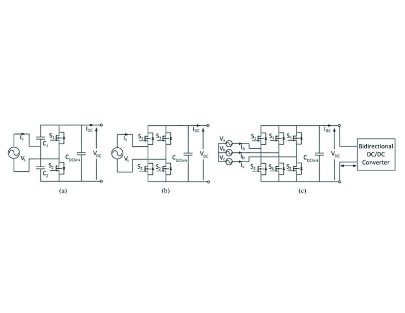
This topology requires more pulse-width modulation (PWM) inputs that add to the complexity and cost of control circuitry. Fig. 4(a)–(c) shows basic bidirectional circuits. Fig. 4(a) shows a single-phase half-bridge bidirectional charger. Fig. 4(b) shows a single-phase full-bridge charger and Fig. 4(c) shows a three-phase full-bridge bidirectional unit that interfaces to a dc-dc converter.
Charger Power Levels and Infrastructure
Charger power levels reflect power, charging time and location, cost, equipment, and effect on the grid. Deployment of charging infrastructure and electric vehicle supply equipment (EVSE) is an important consideration because of many issues that need to be addressed: charging time, distribution, extent, demand policies, standardization of charging stations, and regulatory procedures. Charging infrastructure availability can be used to reduce onboard energy storage requirements and costs.
EV charge cords, charge stands (residential or public), attachment plugs, power outlets, vehicle connectors, and protection are major components of EVSE. They are generally found in two configurations: a specialized cord set and a wall or pedestal mounted box. For this reason, Level 1 and Level 2 charging equipment will be the primary options.

Level 1 Charging: Level 1 charging is the slowest method. In the U.S., Level 1 uses a standard 120 V/15 A single-phase grounded outlet, such as the NEMA 5-15R. The connection may use a standard J1772 connector into the EV ac port. The many existing installed cost of a residential Level 1 charger infrastructure although in general it would be expected that this level will be integrated into the vehicle.
Level 2 Charging: Level 2 charging is the primary method for dedicated private and public facilities. This charging infrastructure can also be on-board to avoid redundant power electronics. Existing Level 2 equipment offers charging from 208 V or 240 V (at up to 80 A, 19.2 kW). It may require dedicated equipment and a connection installation for home or public units, although vehicles such as the Tesla have the power electronics on board and need only the outlet. The new standard has an SAE J1772 ac charge connector on top and a two-pin dc connector below and is intended to enable either ac or dc fast charging via a single connection, as shown in Fig. 5.
Level 3 Charging: Level 3 commercial fast charging offers the possibility of charging in less than 1 h. It can be installed in highway rest areas and city refuelling points, analogous to gas stations. It typically operates with a 480 V or higher three-phase circuit and requires an off-board charger to provide regulated ac–dc conversion. The connection to the vehicle may be direct dc. Level 3 charging is rarely feasible for residential areas. Standards for dc plugs and infrastructure requirements are being set, as shown in Fig. 5. A Japanese protocol known as CHAdeMO is gaining international recognition. Cost of installation is a potential issue.
The SAE J1772 connector for (PHEV and EV) standard prescribes that Level 1 and Level 2 EVSE should be located on the vehicle, while Level 3 is located outside the vehicle. General public stations are expected to use Levels 2 or 3 to enable fast charging in public places. Lower charge power is an advantage for utilities seeking to minimize the on-peak impact. High- power rapid charging can increase demand and has the potential to quickly overload local distribution equipment at peak times. Level 2 and 3 charging can increase distribution transformer losses, voltage deviations, harmonic distortion, peak demand, and thermal loading on the distribution system. Degradation of typical distribution equipment can be mitigated by using a controlled smart- charging scheme. A reliable communication network and control of public charging is needed to enable the successful integration of a large number of EVs.
International Charging Codes and Standards for EVs
The successful deployment of EVs over the next decade is linked to the introduction of international standards and codes, a universal infrastructure, and associated peripherals and user- friendly software on public and private property, as implied in Fig. 6. Safety codes and standards address a wide range of issues relating to EVs. Costs associated with the charging infrastructure correlate with hardware standards. Certain standards are making EV charge infrastructure more complicated and expensive than conventional electrical infrastructure. Article 625-18 of the National Electrical Code, for example, requires that connectors and cables for Levels 2 and 3 be de-energized unless connected to a vehicle. This adds cost to the EVSE. (Vehicle manufacturers generally add an interlock that prevents a vehicle from being driven while on a charge, although this vital feature is not uniform in standards). Some currently available PEVs that are equipped to accept dc fast charging (such as the Nissan Leaf and Mitsubishi i-MiEV) are using the CHAdeMO connector, developed in coordination with Tokyo Electric Power Company. SAE is also working on a “hybrid connector” standard for fast charging that adds high-voltage dc power contact pins to the J1772 connector, enabling the use of the same receptacle for all charging levels. The new standard is expected to be available on EVs in 2013.
Unidirectional Chargers
Two types of power flow are possible between EVs and the electric grid, as shown in Fig. 7. EVs with unidirectional chargers can charge but not inject energy into the power grid. These chargers typically use a diode bridge in conjunction with a filter and dc–dc converters. Today, these converters are implemented in a single stage to limit cost, weight, volume, and losses. High-frequency isolation transformers can be employed and Fig. 8 shows a unidirectional full-bridge series resonant converter for a Level 1 charging system.

Simplicity in the control of unidirectional chargers makes it relatively easy for a utility to manage heavily loaded feeders due to multiple EVs. Those with active front ends can provide local reactive power support utilizing current phase angle control without having to discharge a battery. Research on unidirectional charging seeks optimal charging strategies that maximize benefits and explore the impact on distribution networks. With a high penetration of EVs and active control of charging current, unidirectional chargers can meet most utility objectives while avoiding cost, performance, and safety concerns associated with bidirectional chargers.
Bidirectional Chargers
A typical bidirectional charger has two stages: an active grid-connected bidirectional ac–dc converter that enforces power factor and a bidirectional dc–dc converter to regulate battery current. These chargers can use non-isolated or isolated circuit configurations. When operating in charge mode, they should draw a sinusoidal current with a defined phase angle to control power and reactive power. In discharge mode, the charger should return current in a similar sinusoidal form. A bidirectional charger supports charge from the grid, battery energy injection back to the grid, referred to as vehicle-to-grid (V2G) operation mode, and power stabilization. The topology shown in Fig. 9(a) is a non-isolated bidirectional two-quadrant charger. This circuit has two switches, which greatly simplifies the control circuitry. However, two high-current inductors tend to be bulky and expensive, and it can only buck in one direction and boost in the other. The topology in Fig. 9(b) is an isolated bi-directional dual-active bridge charger. While this circuit provides high power density and fast control, the large number of components can add to cost.
While most studies have focused on bidirectional power flow, there are serious challenges for adoption. Bidirectional power flow must overcome battery degradation due to frequent cycling, the premium cost of a charger with bidirectional power flow capability, metering issues, and necessary distribution system upgrades. Levels 1, 2, and 3 chargers can be unidirectional. Bidirectional chargers are expected only for Level 2 infrastructures because Level 1 power limits and cost targets are low, and it is vital to maximizing flexibility. In Level 3 fast charging, reverse power flow conflicts with the basic purpose and premise of minimizing connection time and delivering substantial energy as quickly as possible.
On-Board and Off-Board Chargers


A charger located inside the vehicle allows EV owners to charge their vehicles wherever a suitable power source is available. Typical on-board chargers limit the power to Level 1 because of weight, space, and cost constraints. Resonant circuits can be helpful. The unidirectional full-bridge series resonant on-board Level 1 charger shown in Fig. 8 is an example. Given that typical power electronics ratings in an EV are at least 30 kW, off-board charging involves redundant power electronics and the associated extra costs. Other disadvantages include the risk of vandalism and added clutter in an urban environment.
This article will be continued in the next issue as Part 2


