
Synchronous condensers play a critical role in modern power systems by providing dynamic reactive power support, short-circuit strength, and inertia essential for grid stability amid increasing renewable integration. Regulators in many countries now advocating installation of synchronous condensers as part of their grid code.
As synchronous condenser operate differently in comparison to synchronous generator so same types of protection scheme and relay setting cannot be adopted for both. Hence effective protection of these machines is therefore vital, particularly the selection and coordination of relay settings that ensure sensitivity, security, and selectivity under a wide range of operating conditions. This review paper analyses current practices, standards, and research developments related to protection and relay parameterization for synchronous condensers. It examines key protection functions – including differential protection, negative-sequence protection, loss-of-excitation, overcurrent, overvoltage, pole slip protection and thermal protection – and outlines typical setting philosophies tailored to synchronous condenser operating modes.
Some protection like Loss of Excitation (LoE) and pole slip requires different approach of analysis for protection of synchronous condenser. Also, this review article shall analyse coordination of various limiters and protection function. Challenges such as high-inertia behaviour, variable excitation, sub-transient dynamics, RE systems transient behaviour and fault contributions are analysed to highlight their implications on relay performance.
Synchronous Condenser
With the increasing push for greener energy resources, power systems worldwide are seeing an accelerated growth in wind and solar energy resources. These renewable generation resources are connected to the grid via power converters or inverters and their performance under transient conditions are significantly different than the Synchronous Machines (SMs) these devices are replacing.
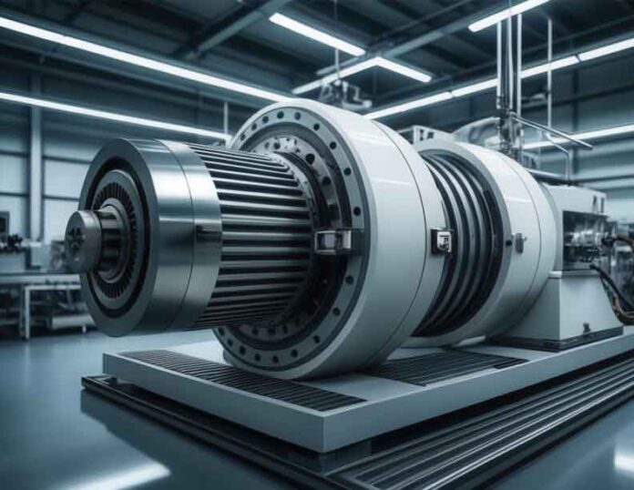
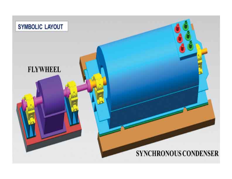
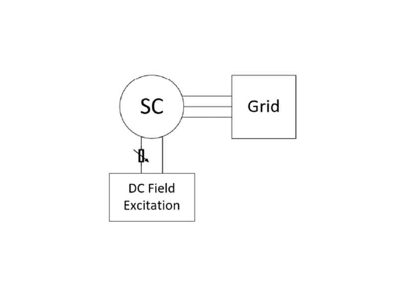
The Synchronous Condenser (SC) as shown in Fig-1, -2 can compensate for system reactive changes and maintain the required System voltage set point by varying excitation or the magnetic field strength of the condenser’s field winding thus generating or absorbing reactive power. It provides short circuit strength to the grid by significant overload capability and fault ride though capability.
Discussion on Protection Function of Synchronous Generator
Stator Ground and Inter-Turn Fault Protection
Stator ground faults are the most common winding failures and can quickly cause serious core damage, if not detected. In air-cooled machines, they may also lead to fire. Since stator differential protection depends on the available ground fault current, separate ground fault protection is usually required.
For low-impedance grounded generators, ground faults are detected using current-based schemes – such as restricted ground fault or neutral directional protection, which provide fast and secure operation. High impedance grounded, unit-connected generators generally use voltage-based methods. By comparing fundamental and third-harmonic voltages at the neutral and terminals, full stator winding ground fault coverage can be achieved.
Inter-turn faults cannot be detected by conventional phase or ground protection. Early detection helps prevent severe damage and long outages. These faults are identified using displacement voltage measured through a broken-delta voltage transformer. A reduction in the affected phase voltage produces a displacement voltage.
Stator Phase Fault Protection
Phase-to-phase faults may occur within slots or at the winding ends. Although less common than ground faults, they produce high fault currents that are not limited by grounding impedance, making fast detection essential.
High-sensitivity differential protection with harmonic restraint is applied to ensure stable and rapid tripping. Additional protection includes overcurrent, voltage-controlled current supervision, negative-sequence current monitoring, and thermal protection to safeguard the machine during unbalanced loading and severe faults. Impedance protection provides time-graded backup for faults in the generator, terminal leads, and unit transformer.
Loss of Prime Mover and Synchronism
A synchronous generator normally supplies active power to the grid. If the prime mover input is lost while the generator remains connected, the machine operates in motoring mode and draws power from the system, which can damage the prime mover. To prevent this, power direction and active power supervision are used along with voltage, current, and frequency monitoring to disconnect the generator. These protections operate as forward or reverse power protection based on power flow direction.
When a generator loses synchronism due to system disturbances, power oscillations may occur, leading to instability. This condition is identified by monitoring changes in apparent impedance at the generator terminals or at the high-voltage side of the unit transformer. The analysis uses the positive-sequence current component, while negative-sequence current is used for blocking. This allows differentiation between power swings originating in the network and those occurring within the generator unit.
In generating mode, the impedance locus typically moves from right to left across the relay characteristic, whereas in motoring operation, such as pump-storage mode, the locus moves from left to right. The shape and direction of the impedance swing depend on the excitation system, governor characteristics, and the initiating disturbance. These impedance variations can be detected using mho-type distance protection.
Loss of Excitation (LOE)
A synchronous generator requires sufficient DC excitation to remain in synchronism with the power system. Under normal conditions, excitation is controlled to supply the required real and reactive power. The generator capability curve defines the permissible operating region, which is primarily limited by the thermal constraints of the rotor and stator.
The generator capability curve defines the permissible operating limits. During normal operation, these limits are set by the thermal ratings of the rotor and stator. In the under-excited region, heating of the stator end iron becomes the primary constraint. Excitation control settings are coordinated with the generator Steady-State Stability Limit (SSSL), which depends on generator impedance, system impedance, and terminal voltage.
The under-excited limiter prevents the excitation system from reducing the field below this stability limit. Partial or complete loss of excitation can force the generator to operate outside the under excited region When excitation is reduced or lost, the generator begins to absorb reactive power from the system instead of supplying it. Under total loss of excitation, the machine operates above synchronous speed and behaves as an induction generator, delivering active power while drawing large amounts of reactive power from the network. The resulting changes in voltage, current, and apparent power are illustrated in the corresponding RMS and power plots.
The most widely used method for loss-of-field protection is the offset mho relay. Installed at the generator terminals, it uses measured terminal voltages and currents to calculate apparent impedance and operates when this impedance enters a defined circular characteristic. The protection typically employs two zones: a fast-operating Zone 1 with a short time delay to protect against severe loss-of-excitation conditions, and a slower Zone 2 with a longer delay to cover gradual loss of excitation up to no-load conditions.
This multi zone approach ensures security during transient events while providing effective machine and system protection. Coordination of the minimum excitation limiter with the mho characteristic prevents leading reactive power operation from encroaching into the loss-of-field zone, thereby avoiding unwanted relay operation during system disturbances.
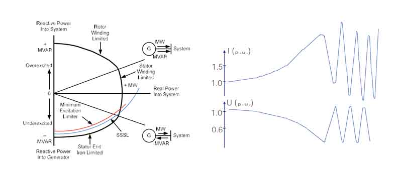
Fig-4: RMS values of U & I during loss of field…
Accidental Energization Protection /Dead Machine Protection
If a generator that is offline and unexcited is accidentally energized while on turning gear or coasting, it operates as an induction motor and can suffer serious damage within seconds. The turbine may also be affected. Since rapid detection is critical, accidental energization protection relies on automatic relay action.
The most dependable scheme uses an instantaneous overcurrent element supervised by a three-phase undervoltage condition, ensuring fast isolation when the generator is energized while not in normal operation.
Review of Novel Concept of Protection Function for Syn Condenser (SC)
Loss of Excitation Protection (LOE)
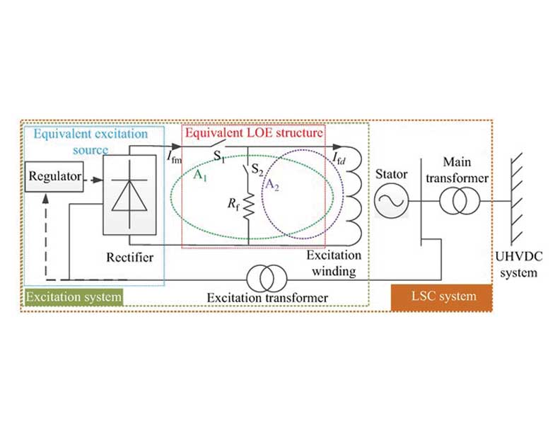
Due to the operational range of Synchronous Condenser (SC) field failure protection is a critical protection. Conventional methods of impedance measurement in negative X axis may not yield desired results as synchronous condenser is supposed to work in low excitation mode during high grid voltage to absorb VAR and to support grid.
One of the essential futures of SC is to absorb reactive power in its leading phase condition, the reverse reactive power feature based on impedance measurement is not typical not enough to detect field failure. Also, SC may be required to operate just around field failure limiter for a longer duration.
SC may be completely or partially lose its excitation through following incidents:
- Field breaker accidental tripping,
- Field open circuit,
- Field short -circuit (flashover of the slip rings),
- Voltage regulation system failure,
- Loss of supply to the excitation.
Events outlined can be classified as Short circuit LOE, Open circuit LOE and partial LOE. Conventional protection based on impedance measurement may not able to distinguish these failure modes of excitation system and can cause maloperation, whereas SC may be required to operate under partial LOE or with no excitation system at all. Based on these criteria other available LOE detection system analyzed as under for their suitability.
Excitation Current Measurement Based LOE Detection
Factor Ko=Ifc/Ifm
Factor Ks= Ifm/ Ifc
Ifc ≈I Ifd,
Ifc: Derived field current
Variation of Ko and Ks for loss of excitation
- OPEN LOE condition: Ko is large, Ks is close to 0.
- SHORT LOE condition: ko is close to 0, Ks is large.
- Partial LOE condition: decrease of Ko and increase of Ks.
Rate of Change of Reactive Power
The first- and second-order derivative of the generator output reactive power versus time can be calculated as:

and
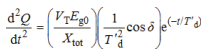
LOE criteria = (dQ/dt) * (d2Q/dt2) < 0 for 0.85 sec.
Flux Measurement Based LOE
Sensors (search coils) placed in the stator wedges directly measure the air-gap flux.
- Field Flux Linkage Estimation: Calculating the field flux linkage participation (FFLP) in the total stator flux linkage using stator voltage and current signals.
- LOE Criteria: Derivative (rate) of flux linkage, is negative or changing rapidly.
Fuzzy Logic/ANN Based LOE Detection
Fuzzy logic-based Loss of Excitation (LOE) detection uses ‘if-then’ rules to interpret imprecise data from a synchronous generator (like terminal voltage, current, apparent impedance) to quickly and reliably identify when excitation is lost.
- Measurement of data: Uses real-time generator parameters like terminal voltage, armature current, real power (P), and reactive power (Q).
- Fuzzification: Converts these crisp (precise) electrical values into linguistic variables (e.g., ‘low’, ‘medium’, ‘high’, ‘decreasing rapidly’) using membership functions.
- Fuzzy Inference Engine: ‘IF-THEN’ rules apply to process these fuzzy inputs.
- LOE criteria: ‘IF voltage is low AND current is high AND impedance is decreasing THEN it might be LOE’.
- Decision: A final threshold determines If an LOE trip is necessary, often combined with analysis of the impedance trajectory on the R-X diagram.
- AI-based LOE Detection
Common AI Techniques Used:
- Artificial Neural Networks (ANNs): Used for classifying patterns in the impedance trajectory or input parameters.
- Support Vector Machines (SVM): Effective for discriminating LOE from other events, sometimes combined with traditional relays.
- Ensemble Methods: Combine multiple models for superior accuracy,
- Hybrid Models: Combining AI with signal processing (DWT) or adaptive neuro-fuzzy systems.
For synchronous condenser excitation current measurement, rate of change of reactive power and flux measurement looks more promising. New methods like ANN and AI based methods requires more data for validation of the models before actual implementation in protection system of synchronous condenser. It is expected that protection function for LOE may be based on one more LOE detection methods outlined as above.
Out of Step /Pole Slip Protection/Over Current/Negative Phase Sequence
Synchronous condenser has no prime mover or load connected to its rotor. As such, there are no external forces to cause a pole slip as the machine free spins to follow the grid frequency. Also, synchronou condenser draws MW from grid only to meet the resistive loss component. While synchronous condensers may not be completely immuned to transient instability, they are significantly more resilient than synchronous generators.
Moreover, out of step or pole slip is severe to machine when it is in operation at full MW capacity. Syn condenser rarely operates at a higher MW. Thus, out of step, pole slip, over current and negative phase sequence setting to be adopted based on machine actual MW rating after due deliberation with manufacturer.
Reverse Power Protection/Low Forward Power Protection:
As these types of machines intended to draw power from grid setting to adopted based on quoted loss figure by the manufacturer.
All other protections which are machine specific shall remain same as that for a conventional synchronous generator till new function realization of same function is not established.
Coordination of Protection Scheme and Limiters for Synchronous condenser
Under Excitation Limiter / Loss of Field Protection
In applications, where the condenser installation is needed to consume significant VARs to correct system voltage issues, the under-excitation limiter may be disabled in the excitation controls altogether.
If the excitation is lost due to an abnormal event or fault on the excitation circuit during an intentional motoring scenario, the condition cannot be directly detected via field current. More sophisticated excitation system installations can be configured to detect this LOE condition via its voltage regulator. When the regulator does eventually attempt to push more current to increase VAR output, it will trigger an alarm state that trips after a set time delay.
Field Overexcitation Limiter / Protection
In line to IEEE C50.13 working group and NERC’s PRC-019 rotor thermal limit needs to be coordinated with condenser overexcitation protection. Thermal limit equation can be used for such coordination.
Condenser Overexcitation Limiter / Protection
Overexcitation of a synchronous condenser occurs when the ratio of the voltage over frequency on the machine stator exceeds its capabilities. During this condition, stray flux generated may cause eddy currents in the machine laminations and overheating that can break down insulation. Volts per hertz (V/Hz) protection should be set in excitation controls and/or the protective relaying for the condenser to prevent this from occurring.
Conclusion
Due to higher level of RE incursion in to grid, VAR management and voltage profile control will be a difficult task in future. To mitigate grid planner and controller may go for large scale installation of synchronous condenser. As synchronous condenser has more capabilities wrt inertia so installation of synchronous condenser along with RE plant will be a new norm.
As discussed, protection of synchronous condenser is different from that of a conventional synchronous machine. Protection philosophy outline in the article needs to be deliberated between manufacturer, regulator and operator so as to design a comprehensive protection and control scheme for synchronous condenser.

Debasisa Rath is the General Manager (Electrical), PEM at Bharat Heavy Electricals Ltd., Noida. He has more than 36 years of experience in the power sector, covering engineering, project execution, operation, maintenance, and consultancy services for large utility-scale thermal power stations and Nuclear plant. received the Bachelor’s degree in Electrical Engineering (VSSUT Burla) and the Master’s degree (M. Tech.) in Power Generation Technologies from IIT Delhi.