Self-supported fluid-filled outdoor terminations have been successfully used as long as high-voltage cables have existed, and they continue today to be the network operator’s first choice due to their excellent long-term performance record. The basic construction of a modern fluid-filled termination consists of a composite supporting insulator and a silicone rubber stress cone installed onto the cable insulation; the remaining space within the construction is filled with silicone oil compound (1). The main advantages of this modular design are its wide application range of cable types and sizes and its easy adaptation to the environmental and mechanical requirements of the cable installation site. Thanks to the remarkable properties of the silicone oil, this design is preferred not only due to its excellent electrical performance but also as an environmentally friendly solution. Although the terminations are extremely reliable and safe, electrical breakdowns cannot be totally avoided. The worst-case failure is the occurrence of an internal power arc as result of an electrical breakdown. The very high temperature of the electrical arc can cause a rash vaporization and thermal expansion of the insulating medium. As a result of the high overpressure within the termination, an explosion of the construction may occur, resulting in scattering of the debris of the termination that may produce serious damage to property, other equipment, or even human life.
For cable installations very close to valuable property or public areas, Brugg’s explosion-resistant outdoor terminations provide a cost-effective and reliable solution.
Presented here are conclusions from the main development challenges and the basic functional principles of the patented solution and results obtained from type tests and field installations.
Mechanical stress produced by internal power arcs on outdoor terminations
During an internal arc in a termination, the electrical discharge channel in the form of plasma causes a fast phase transition of the insulating medium from liquid to vapor, thus producing a sudden increase of pressure in the vapor phase. This phenomenon generates pressure waves that stress the entire construction.
If the developed dynamic stress is at any time higher than the admissible mechanical strength of one or more termination components – the hollow insulator body, top and bottom flanges, or the fixing bolts that fasten the termination to the foundations of the supporting structure – a mechanical breakdown of the termination itself or its support may occur, with projection of debris all around the installation.
There are fundamentally two options for addressing this problem. The first option is to design a termination able to withstand the high pressures developed during an internal electrical breakdown. However, this approach leads to excessive over engineering of the components mentioned above, which will strongly limit the field of application of such a solution. Consequently, this approach can only partially solve the problem.
A second and more effective approach is a controlled release of the internal pressure in the early stages of a power arc, thus limiting the maximum overpressure and the projection of debris that may follow. To achieve this result, the termination should have embedded pressure release devices able to operate within a few milliseconds after the ignition of the internal arc.
Design of pressure release devices
Following the second design approach, the main challenge during the development phase was to design a reliable pressure release device. As a limiting condition, such a device must be capable of releasing the pressurized fluid in less than 2 ms after the arc ignition, while ensuring the necessary mechanical strength for prolonged, safe service at the pressure levels of normal operation conditions. Starting from the well-proven design of Brugg’s outdoor termination with hollow insulators, a way of integrating the pressure release devices into the termination had to be found. As a result, the pressure release devices were placed on the top of the termination (integrated in the corona shield) and at the bottom (integrated into the base plate of the termination) (Fig. 1).
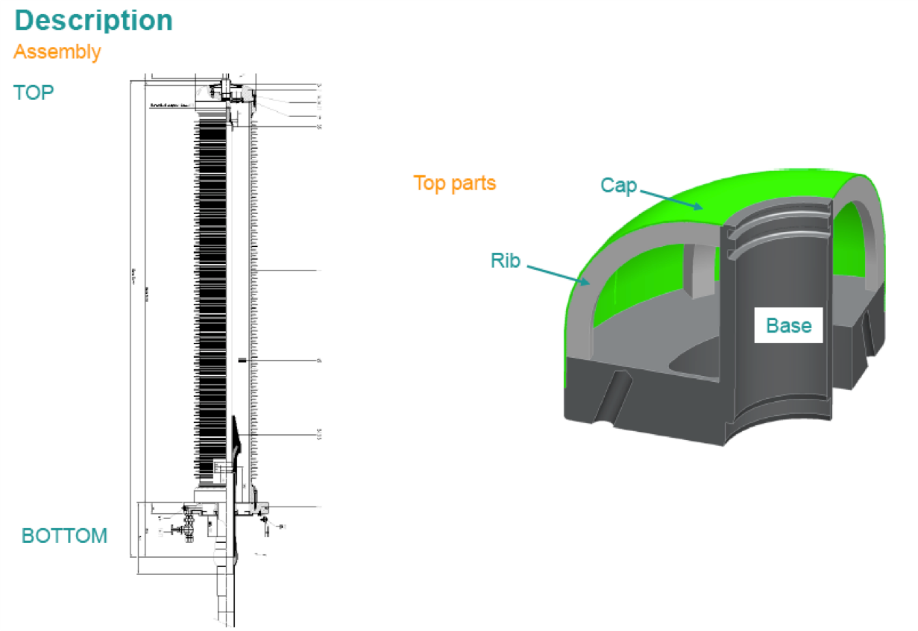
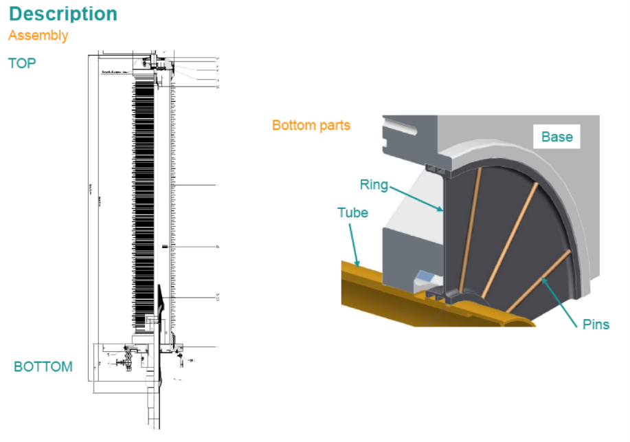
Fig. 1: Position of pressure release devices at the top and bottom of the termination
Although they have different shapes, both devices act similarly to a burst disc, albeit with different dynamics. In order to minimize the experimental activity and limit it only to a final development stage, the design phase required a large use of finite element method analysis.
To work as corona shield, the pressure device at the top of the termination takes the shape of a cap with 8 grooves that break at a predefined mechanical stress, allowing the cap to open like a tulip flower (Fig. 2).
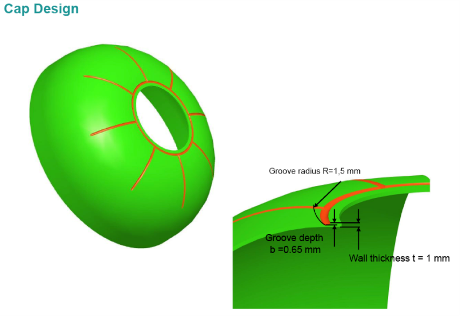
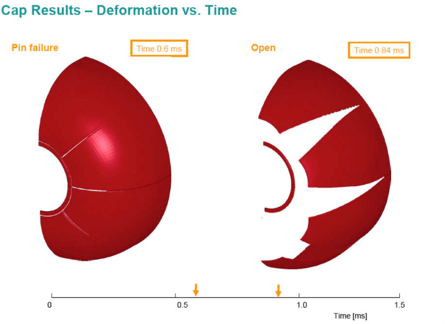
Fig. 2: Working principle of pressure release device at the corona shield
The pressure device placed at the bottom of the termination is integrated into the gland of the termination and is supported by pins fastened to the base plate (Fig. 3). When a predefined pressure is reached, the disc is expelled in an axial direction to the bottom of the termination.
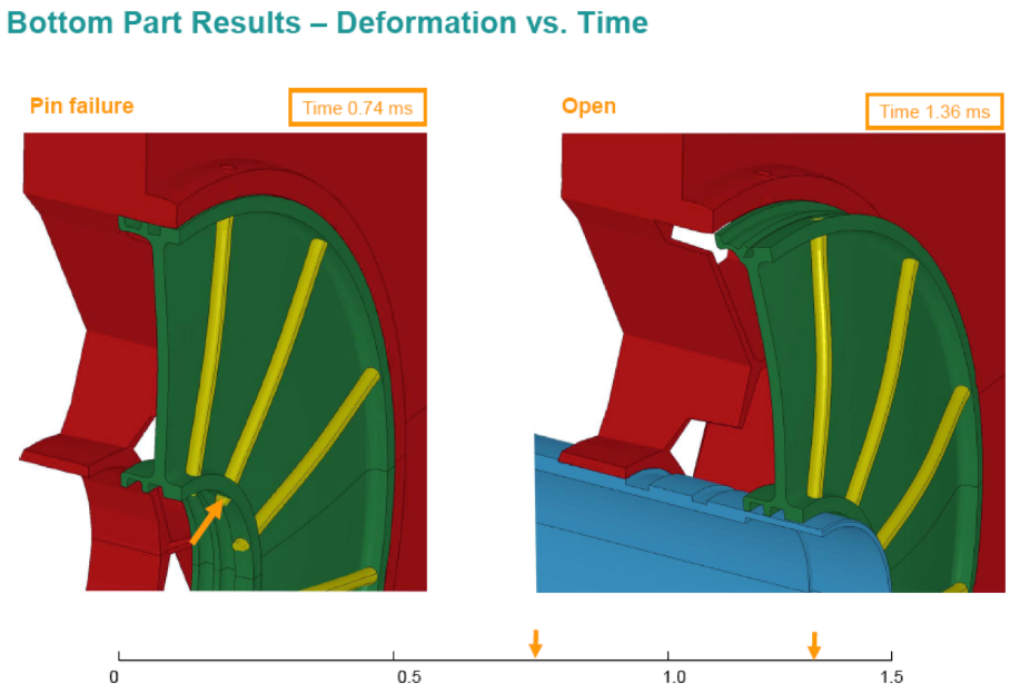
Fig. 3: Working principle of pressure release device at the base plate
Type test of a 400 kV outdoor termination
To classify an outdoor termination as resistant to internal power arcs, the solution is tested according to European standard HD 632:2008 S2 (2). The standard stipulates that no debris shall be found beyond 3 meters from the test object after the test.
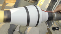
Fig. 4: Installation of 1.5 mm2 copper during termination assembly for power arc testing
The internal arc test is conducted for a duration of 0.5 seconds and is performed in a single-phase test circuit with a supply voltage of 20 kV and a symmetrical 50 Hz short-circuit current of 63 kA provided by a 2,500 MVA power generator. To induce an internal power arc in the termination, the test setup consists of a short-circuiting the cable conductor to the cable screen with a 1.5 mm2 copper wire (Fig. 4) prior to the final assembly of the termination. The test object arrangement prior to and during the test is shown in Fig. 5.
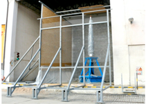
Fig. 5: Internal power arc test of a 420 kV outdoor termination
Field installations
The installation of explosion-resistant outdoor terminations requires no special measures on-site, besides reinforced support to counteract the force following the rapid release of oil. By following its basic modular configuration, this type of termination is installed in practically the same manner as a conventional one. Both pressure release devices are pre-assembled at the factory and under controlled quality procedures prior to the delivery, thus minimizing the risk of undesirable installation errors.
Since their release in 2011, around 20 units for 150 kV and 51 units for 220 kV cable systems have been installed by the Italian TSO Terna and are currently in service (Fig. 6). Since then the demand for explosion-resistant outdoor terminations has significantly increased, with more than 120 installations per year worldwide for voltage systems up to 245 kV.
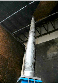
Fig. 6: 420 kV outdoor termination after the power arc test
Fig. 7: Installation of 245 kV cable system close to a highway, Turin, Italy
Conclusions
Brugg’s design for an explosion-resistant outdoor composite termination has been described here, together with the relevant testing activity. The integration of an overpressure release device in Brugg’s composite outdoor termination design represents a reliable solution to minimizing consequential damage in the event of an internal arc in an oil-filled outdoor termination.
Ease of installation and no additional maintenance compared to other terminations allow this product to be integrated as a standard component in any network. Only some reinforcement of the steel structure to counteract the pressure wave will be required.