
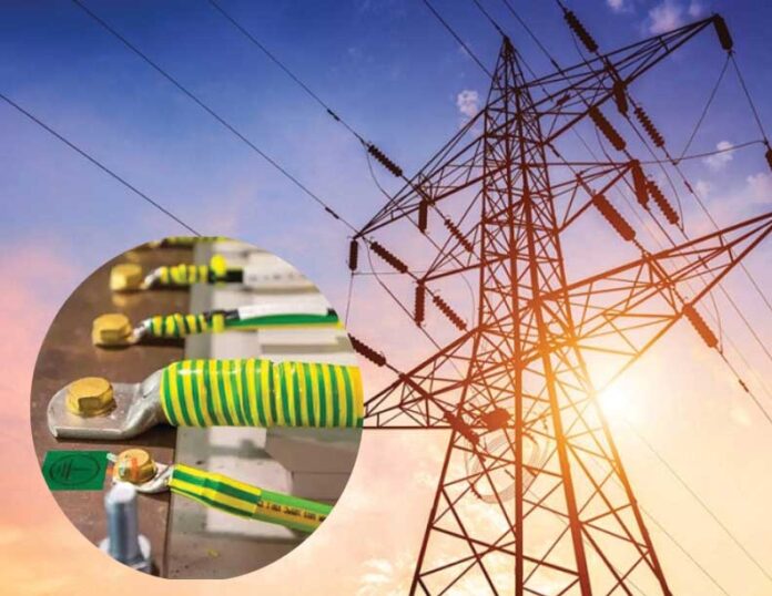
Earthing (grounding) is to make an electric connection between a conductive part and a local earth. This is a fundamental concept in electrical installations, providing a path for fault currents and helping ensure electrical safety.
It prevents electric shock hazards, limits overvoltages, and ensures the proper operation of protective devices. There are several earthing systems in use worldwide, primarily classified as TN (Terre-Neutral), TT (Terre-Terre) and IT (Isolated Terre).
Significance of Earthing (Grounding)
- Safety from Electric Shock
- Protection against Electrical Fires
- Equipment Protection
- Voltage Stabilisation
- Legal and Regulatory Compliance
Concept of Earthing (Grounding)
When the neutral for any system is not connected with the earth then it will be known as electrical system without earthing as depicted in figure 1.
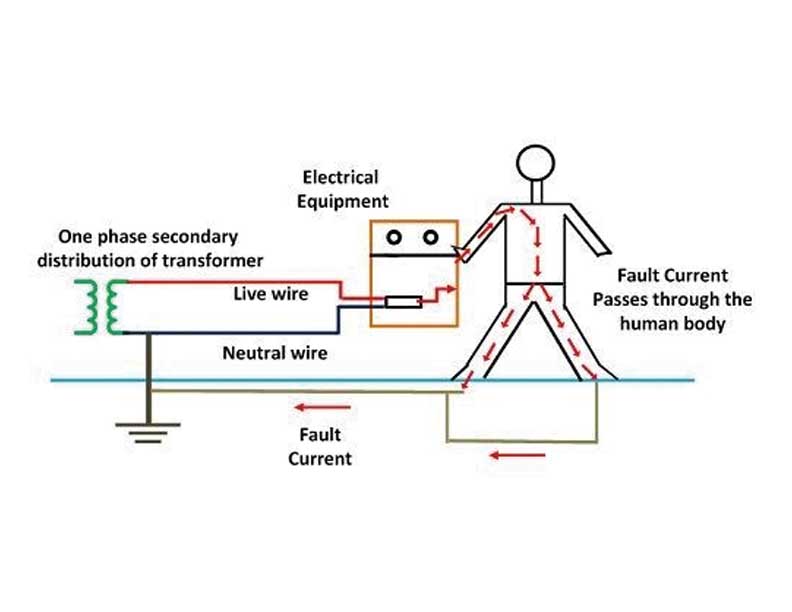
Mostly, the galvanised iron is used for the earthing. The earthing provides the simple path to the leakage current and fault current in the system. The short-circuit current of the equipment passes to the earth which is assumed to have zero potential. Thus, protects the system equipment and personnel working with these equipment from damage as well as shock current as shown in figure 2.
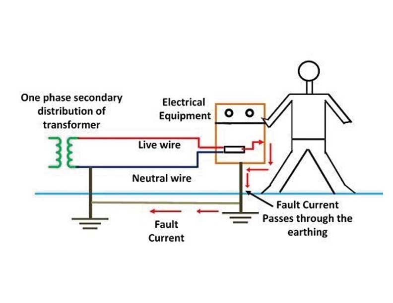
The system earth resistance should be such during any fault against which earthing is designed to ensure protection i.e., the protective gear must operate to isolate the faulty section – for example by circuit breaker or fuses.
Types of Electrical Earthing
The electrical equipment mainly consists of two non-current carrying parts. These parts are neutral of the system or frame / support structure of the electrical equipment. From the earthing of these two non-current carrying parts of the electrical system, earthing can be classified into two types:
- Neutral (System) Earthing
- Equipment Earthing
- Neutral (System) Earthing: In neutral earthing, the neutral of the system is directly connected to earth with the help of some metallic conducting wire. The neutral earthing is also called the system earthing. Such type of earthing is mostly provided to the system that has star winding. For example, the neutral earthing is provided in the generator, transformer, DG set etc., as shown in figure 3.
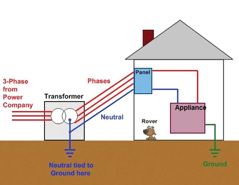
- Equipment Earthing: Such type of earthing is provided to the electrical equipment. The non-current carrying part of the equipment like their metallic frame is connected to the earth by the help of the conducting wire as shown in fig 3. If any fault occurs in the apparatus, the short-circuit current to pass the earth by the help of wire. Thus, protect the system from damage.
Classification of earthing system
A low voltage (LV) distribution system may be identified according to its earthing system. These are defined using the five letters:
- T (direct connection to earth),
2. N (neutral),
3. C (combined),
4. S (separate) and
5. I (isolated from earth).
The first letter denotes how the transformer neutral (supply source) is earthed, while the second letter denotes how the metal work of an installation (frame) is earthed. The third and fourth letters indicate the functions of neutral and protective conductors respectively.
There are three possible configurations:
- TN: transformer neutral earthed, frame connected to neutral. The TN system includes three sub-systems: TN-C, TN-S and TN-C-S.
- TT: transformer neutral earthed and frame earthed.
- IT: unearthed transformer neutral, earthed frame.
TN Earthing System
In a TN earthing system, the supply source (transformer neutral) is directly connected to earth with one or more conductors and all exposed conductive parts of an installation are connected to the neutral or protective earth conductor. The three sub-systems in TN earthing system are described below with their key characteristics.
TN-C Earthing System
TN-C system has the following features:
- Neutral and protective functions are combined in a single conductor throughout the system. (PEN – Protective Earthed Neutral).
- The supply source is directly connected to earth and all exposed conductive parts of an installation are connected to the PEN conductor as shown in figure 4.

Safety Protection:
- Fuses or circuit breakers for overcurrent protection.
- RCDs are generally not effective without separate PE.
Applications:
- Often used in older or budget-limited distribution networks.
TN-S Earthing System
TN-S system has the following features:
- A TN-S system has separate neutral and protective conductors throughout the system.
- The supply source is directly connected to earth. All exposed conductive parts of an installation are connected to a Protective Conductor (PE) via the main earthing terminal of the installation as shown in figure 5.
Safety Protection:
- Residual Current Devices (RCDs) or Miniature Circuit Breakers (MCBs) detect faults between live and earth.
- Overcurrent Protection Devices (OCPDs) trip if excess current flows.
- Quick disconnection during earth faults to prevent shock.
Applications:
- Commercial and industrial installations where electrical noise reduction is essential.
TN-C-S Earthing System
TN-C-S earthing system has the following features:
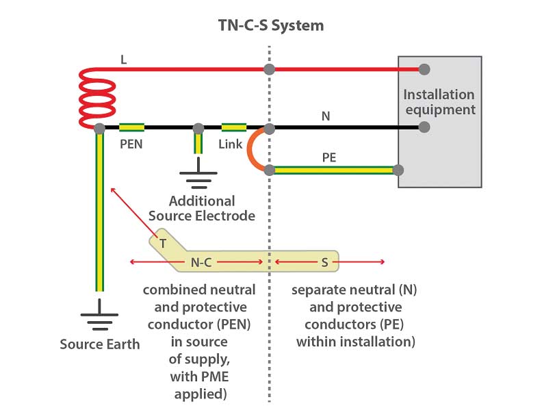
- Neutral and protective functions are combined in a single conductor in a part of the TN-C-S system. The supply is TN-C and the arrangement in the installation is TN-S as depicted in figure 6.

- Use of a TN-S downstream from a TN-C.
- All exposed conductive parts of an installation are connected to the PEN conductor via the main earthing terminal and the neutral terminal, these terminals being linked together.
This type of distribution is known also as protective multiple earthing and the PEN conductor is referred to as the Combined Neutral and Earth (CNE) conductor.
The supply system PEN conductor is earthed at several points and an earth electrode may be necessary at or near a consumer’s installation.
Safety Protection:
- RCDs to detect leakage currents
- Equipotential bonding to reduce touch voltages
- Multiple earthing points to minimise rise in earth potential
Applications:
- Residential, commercial and mixed-use installations
TT Earthing System
In this system, the supply source has a direct connection to earth. All exposed conductive parts of an installation also are connected to an earth electrode that is electrically independent of the source earth as shown in fig 7.
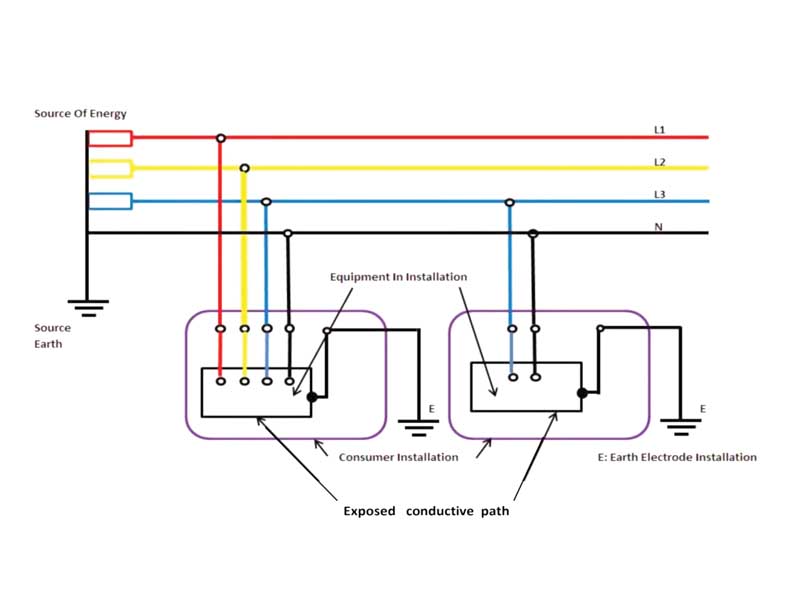
The fault loop impedance is higher, and unless the electrode impedance is very low indeed.
Safety Protection:
- RCDs are mandatory, typically 30 mA for personal protection
- Earth electrodes must have low resistance to ensure proper fault current flow
- Earth loop impedance testing is crucial during installation
Applications:
- Rural or remote areas
- Small buildings with no PME availability
IT Earthing System
- In this system, the supply source is either connected to earth through deliberately introduced high earthing impedance (Impedance earthed IT system) or is isolated from earth. All exposed conductive parts of an installation are connected to an earth electrode as shown in figure 9.
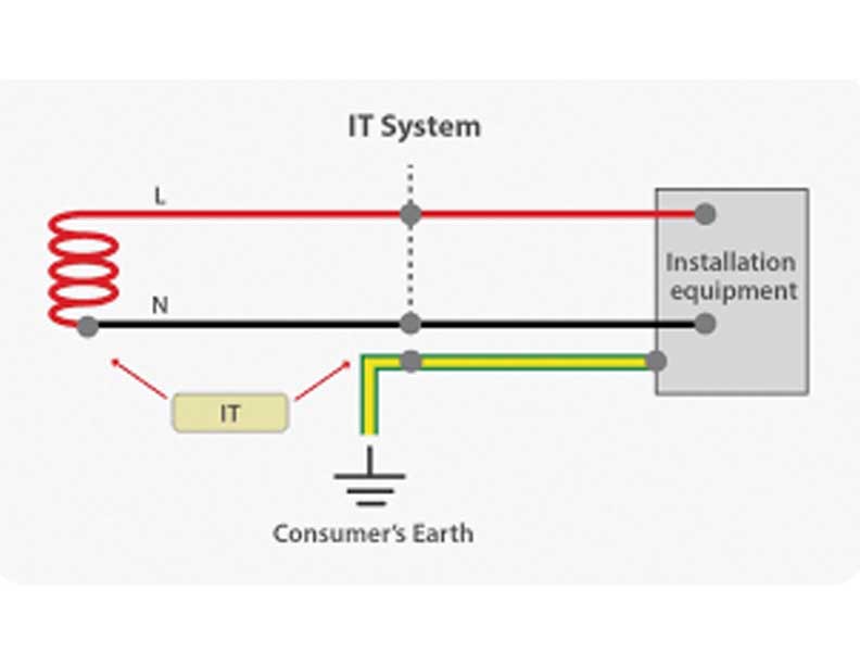
- The conductive parts including metal body of the installations are connected to earth through one or more local earth electrodes. These local electrodes do not have any direct connection to the source.
- It is pertinent to mention here that single phase IT system shown in figure 8 is not used in India (Except in special locations).
Safety Protection:
- Insulation Monitoring Devices (IMDs) detect the first fault without shutting down the system.
- Alarms or indicators alert personnel of insulation failures.
- RCDs and MCBs may be used for secondary fault protection.
Applications:
- Hospitals (operating theatres)
- Mines, military, ships
- Data centres
Comparison of all earthing systems
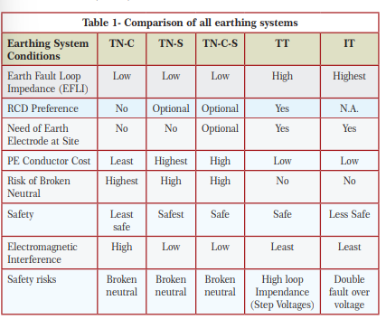
Comparison of all earthing systems based on earth fault loop impedance, RCD preferred, need earth electrode at site, PE conductor cost, etc., has been carried out as follows:
Earthing and bonding difference & significance
Earthing and bonding are both vital safety measures in electrical systems but serve different purposes. Earthing connects electrical equipment or systems directly to the earth to safely dissipate fault currents, preventing electric shock and equipment damage. It provides a reference point of zero potential and ensures protective devices operate correctly during faults (As already discussed in detail).
Bonding, on the other hand, involves connecting all exposed and extraneous conductive parts together to maintain equal potential and eliminate voltage differences between metal parts. While earthing directs fault current to the ground, bonding prevents electric shock by ensuring all accessible conductive surfaces remain at the same potential. (Refer figure 9)

Equipotential bonding in an electrical system is the practice of electrically connecting all exposed and extraneous conductive parts to maintain the same potential and minimise voltage differences. This connection ensures that, in the event of a fault, no dangerous potential exists between metallic parts that a person might touch simultaneously. Let’s understand the terms exposed and extraneous conductive parts. (Refer figure 10)
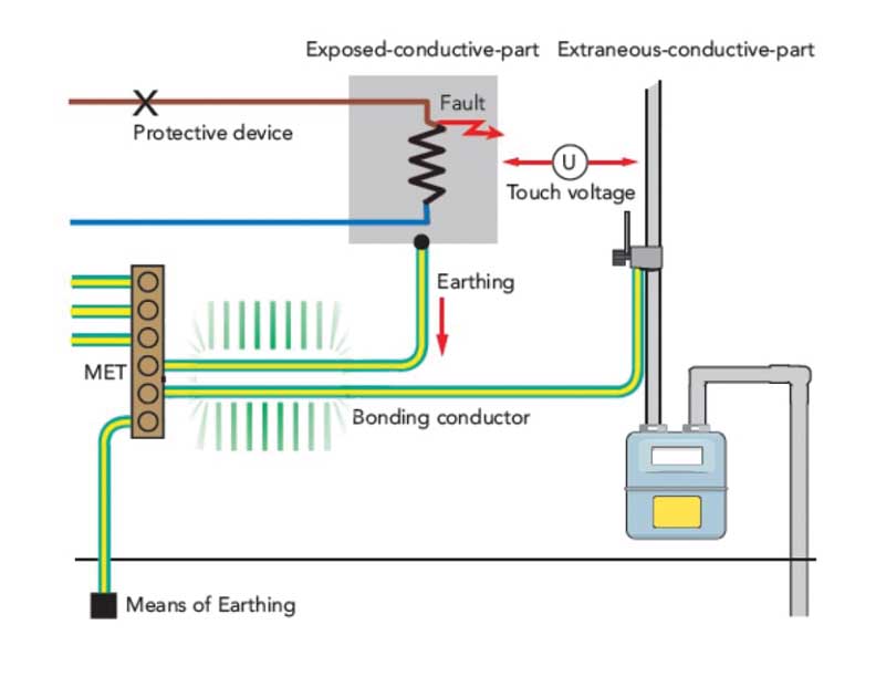
Protection: Must be connected to the main earthing terminal via equipotential bonding to ensure they are at the same potential as exposed parts, preventing dangerous touch voltages.
Equipotential bonding is achieved through main and supplementary bonding conductors. Its primary purpose is to enhance safety by reducing the risk of electric shock, providing a low-resistance fault path, and enabling protective devices to disconnect faulty circuits promptly.
Main bonding and supplementary bonding are essential safety measures in electrical installations designed to prevent electric shock and ensure proper operation of protective devices. Main bonding involves connecting the main protective conductor to the main metallic parts of a building, such as gas, water, or structural steel pipes. This creates a common reference point for all metallic parts, ensuring that, in the event of a fault, no dangerous voltage difference exists between them. It also allows protective devices like circuit breakers or fuses to operate quickly by providing a low-resistance fault path.
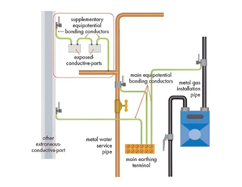
Supplementary bonding, on the other hand, is the additional connection between exposed conductive parts and nearby extraneous conductive parts in locations where the risk of electric shock is higher, such as bathrooms or kitchens. It equalises potential differences within a localised area, reducing the risk of current passing through a person who simultaneously touches two metal surfaces at different potentials. (Refer figure 11).
Regulation 18 – Earthed terminal on consumer premises
What it requires:
The electricity supplier must provide and maintain a proper earthed terminal on the consumer’s premises.
For installations with voltage exceeding 250 V, the consumers must provide their own earthing systems (an independent electrode) that must be inter-linked with the supplier’s earthed terminal via a suitable link.
The consumer must take all reasonable precautions to prevent mechanical damage to the earthing terminal and its lead belonging to the supplier.
Why it matters:
- Proper earthing is critical for protecting persons and equipment from fault currents and electric shocks. (Refer figure 12)
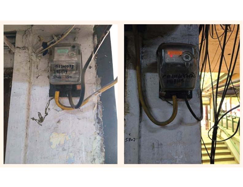
- Ensures that the supplier and consumer’s earthing systems are coordinated, reducing risk from improper or missing earth connections.
Key points to remember:
- Applies to every consumer’s installation where supplier provides supply.
- If voltage > 250 V, consumer’s own electrode is mandatory and must link with supplier’s earth.
- Both supplier’s and consumer’s earth arrangements must be maintained and protected from damage.
Conclusion
Choosing the right earthing system is essential for ensuring electrical safety, reliability, and compliance with regulations. Each system has its unique structure, benefits and associated protection mechanisms.
Proper design, installation and maintenance of the earthing and protection systems are crucial for minimiing electrical hazards, ensuring user safety.
Earthing and bonding are two different ways of providing safety to electrical systems from sudden and unexpected leakage or discharge of current due to various reasons. Though earthing is a more common term we come across, bonding is also equally important in all electrical systems. At the same time, electrical bond alone does not ensure complete protection, but along with grounding, it helps to discharge the extra current to the ground thus making the system safe.
As per regulation 18 of CEA safety regulation it must be ensured that the supplier and consumer’s earthing systems are coordinated, reducing risk from improper or missing earth connections.

Dr. Rajesh Kumar Arora obtained his B. Tech. and M.E. degrees in Electrical Engineering from Delhi College of Engineering, University of Delhi. He completed his PhD in grounding system design from UPES, Dehradun. He is also a certified Energy Manager and Auditor and has worked in 400kV and 220kV Substations for more than 14 years in Delhi Transco Limited (DTL). He has also worked as Deputy Director (Transmission and Distribution) in Delhi Electricity Regulatory Commission (DERC). Presently he is working in D&E (Design and Engineering) department of DTL.