

Earthing is very important, since a large number of faults involve earth are caused due to thunderstorm or lighting strokes. The term earthing and grounding have the similar meaning and it means of making a connection between the equipment under protection and the general mass of the earth. The main purpose of grounding is to minimize the effect of transient overvoltage occurred due to lightning stroke, in accordance with the standards for personnel safety and for assisting the rapid detection and isolation of the fault areas. Earthing connections are accomplished by driving earth electrode into several different-different places of the earth. Earth electrode is of a metal plate, metal pipe or metal conductors electrically connected to the earth and the equipment to be earthed. The material used for earth electrodes is made up of copper, aluminum, mild steel and galvanized iron. The factors that affect the earth resistance of an electrode or group of electrodes includes the composition of the soil in the immediate neighborhood, the temperature of the soil, the moisture content of the soil and the depth of the electrode. Thus, the composition of a soil gives an indication about good soil resistivity. Soil resistivity measurement is normally carried out for determining the actual value of the soil resistivity under the changing weather conditions in which an electrode is installed.
We know that the resistance of an earth electrode depends upon the resistivity of the soil in which the electrode is inserted and hence, soil resistivity measurement is an important parameter when designing earthing installations. In this paper, fall-of-potential method is used for the measurement of effective resistance of earth terminals.
Resistance is that property of a conductor which opposes the flow of electric current when a potential difference is applied across the two ends of that conductor. Resistance is the ratio of the applied voltage (V) to the flow of electric current (I) as defined by Ohm’s Law i.e.,
V = I x R …. (1)
V is the Potential Difference across the conductor
(Volts)
I is Current flowing through the conductor in
(Amperes)
R is Resistance of the conductor in (Ohms)
The resistivity of the soil varies widely throughout the world and changes throughout the year. Soil resistivity is determined by the content of its electrolyte which consists of moisture, minerals, and the dissolved salt in it. It impacts on the overall sub- station resistance and how much earth electrode is required to achieve the desired values of earth resistance. The lower the resistivity the shorter electrode is required to achieve the desired earth resistance value. It is an advantage to know the resistivity at the planning stage as it gives an indication for how much electrode is required. When selecting the test technique for soil resistivity, factors such as probe depth, lengths of cable required, efficiency of the measuring technique, cost and ease of interpretation of the data need to be considered.
Resistance of the earth of any earth electrode is influenced by the resistivity of the surrounding soil. This depends to a large extent on the nature of the soil with its moisture content. Since soil exhibits a resistance to the flow of electrical current and is not an ideal conductor. There is always some resistance between the earth electrode and “true Earth”. This resistance is called earth resistance of an electrode and it depends on the soil resistivity, the type and size of the electrode and the depth to which it is buried into the ground. The most commonly used method for measuring the earth resistance of an earth electrode is the fall-of- Potential method. It is the most recognized method for measuring the resistance of the earth of an earthing system. This method is based on IEEE standards. It is suitable for use in circumstances such as transmission line structure.
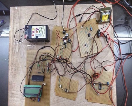
Components & Methods
Fall-of-Potential method is used to determine the earth resistance. The following listed equipment are used for the measurements of resistance of earth electrode.
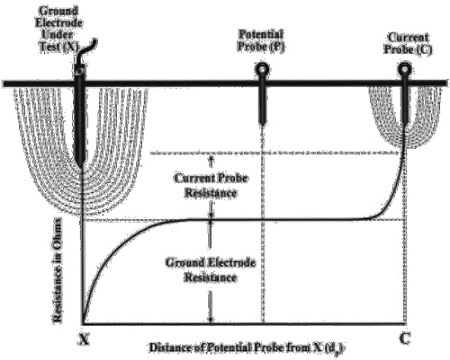
In this method, three points of ground contacts are considered that consist of the earth electrode under test, a current probe which is inserted at adequate distance from the earth electrode which is under test and voltage probe which is inserted at some distance between the probe under test and the current probe. With this method, the Digital Earth Tester is used to inject current into the tower footing earth electrode under test. The current then flows through the earth to the remote current probe and returns to the tester. As the current flows through the earth a voltage drop is created. This voltage drop is proportional to the amount of current flow and the resistance of the earth electrode to earth. The voltage probe was used to measure this voltage drop and the meter then displays both the amount of current flow and the resulting voltage drop. The resistance measured at several locations moving the voltage probe at regular intervals, each of them equal 10% distance of probe under test and current probe. The resistance value then displayed by display of Digital Earth Tester.
During measurement, the position of the current probe was moved far enough away from the earth electrode under test so that the voltage probe can lie outside the effective resistance areas of both the earth electrode and the other test electrode. This is because there may be overlapping of the resistance areas which can cause a steep variation in the measured resistance.
Setup
Procedure of Testing
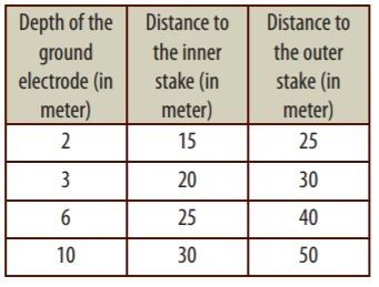
• Three rods are inserted into the ground as per norms of IEEE.
• One rod is reference rod and other two rods are for current and voltage measurement respectively.
• The circuit is connected with the rods through the clamps.
• After this switch on the device and take readings.
• After one reading, move the voltage rod and observe the change.
• Take at least four readings for accuracy purpose.
• Thus readings are taken and the device is switched off.
Results
Conclusion
The Earth Resistance measurement could be carried out at selected points along its route. The Earth Resistance profile varies between 10 Ohms and 20 Ohms. Soil identifications as well as programmed intensive field measurements of soil resistivity and earthing system at selected sites proves that soil resistivity values’ depend on the type of soil. In rocky areas, the resistance could be lowered by a buried network of well-designed earth mat or by a network of buried counterpoise earth wire in order to reduce the effect of lightning stroke. For better earthing of electrical systems the soil resistivity should be improved for effective earthing of system.
If you want to share thoughts or feedback then please leave a comment below.


