Smart City Mission is an initiative of Govt of India to drive economic growth and improve quality of life. Assured electricity supply is one of the core infrastructure elements of a Smart City along with water supply, sanitation, robust IT connectivity, public transport etc. In 2015, Govt of India announced a list of 100 smart cities. The requirements of a Smart City are defined under Smart City Mission of Ministry of Housing and Urban Affairs. A Smart City would include gardens, parks, water bodies, river fronts and also different types of land uses like residential, commercial, industrial, IT, hospitals, hotels etc. This article covers the various aspects of power distribution system design in smart cities.
Key Features
The key features of the power distribution system shall be as follows:
- Reliability- Uninterrupted and Quality supply
- Smart
- Sustainable
- Expandable.
Power Distribution Arrangements
The power distribution arrangements consist of different options. Some of the options are:
Option 1: State electricity distribution company (DISCOM) or other distribution licensee shall develop, operate and maintain the entire electrical infrastructure up to the consumer meter.
Option 2: Special Purpose Vehicle (SPV) formed for the implementation of a Smart City Project shall acquire a franchisee license from a Distribution Licensee or itself can become a Distribution Licensee to develop, operate and maintain the entire electrical infrastructure for the power distribution beyond the supply point of DISCOM till the metering points of the end-users.
Option 3: Local private developer shall acquire a Franchisee license from Distribution Licensee to develop, operate and maintain the entire electrical infrastructure for the power distribution beyond the supply point of DISCOM till the consumer metering points. This will be applicable for private townships.
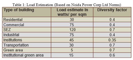
Load Estimation
The load estimation for different types of land uses will be based on guidelines available from state electricity boards/local power supply agencies/supply codes of state regulatory body. The estimate will take in to account the load density, area wise diversity factor, FSI and occupancy factor. Some typical values for estimate are given for reference in Table 1.
The total load estimate for the entire set up is calculated based on the built-up area of individual types of land use and as per the load considerations mentioned above. Each type of consumer will have different diversity factors based on which the operating load is estimated. Further there will be an overall diversity factor between different types of land use. This will give the estimated maximum demand for the city/area.
Depending upon the scale of the project the period of implementation can extend up to more than 20 years and the project is likely to be implemented phase wise. In such cases the demand estimation will be done phase wise and a modular expandable system shall be designed.
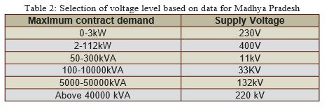
Selection of voltage level
The selection of voltage level depends upon the guidelines of state electricity supply code formulated by State Electricity Regulatory Commission (SERC). A typical case for Madhya Pradesh is mentioned here for reference. However the same is case specific and will have to be discussed with local electricity board depending upon the location of the project. Typical values for supply voltage level are given in Table 2.
The supply voltage of the project at every level i.e. from individual plot to the entire development area in the city shall be decided based on the above.
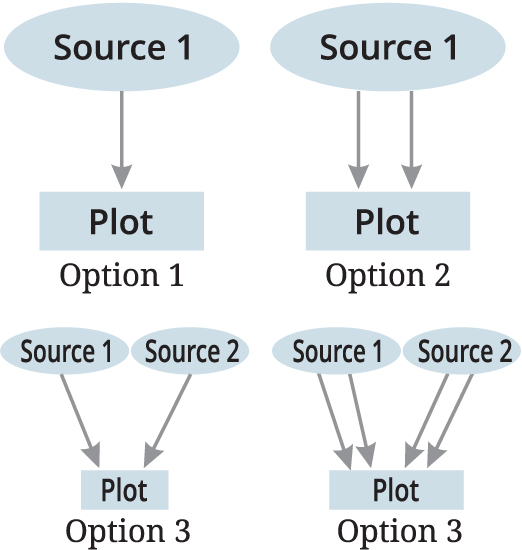
Scheme for Transmission Line
After deciding the supply voltage level as mentioned above, a survey shall be carried to identify the source in consultation local EB. Following options shall be considered:
Option 1: Single circuit transmission line from one power source in substation.
Option 2: Double circuit transmission line from one power source in substation.
Option 3: Single circuit transmission line from two different power source substations.
Option 4: Double circuit transmission line from two different power source substations.
The pros and cons will be evaluated based on the criticality of the project, contract demand and the extent of redundancy required before arriving at a final decision.
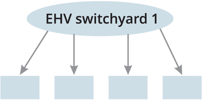
Scheme for EHV Switchyard
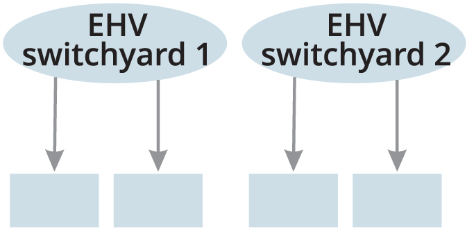
The EHV switchyard could be either be GIS or AIS. The decision will be based upon space/time and cost constraints. Further two alternatives are possible viz a single switchyard for the entire premises or two switchyards. The single switchyard will be planned as far as possible at the load centre. In case of two switchyards both will be interconnected for better redundancy. The schematic for Alternative 1 is given in Fig 1 and that for Alternative 2 is given in Fig 2.
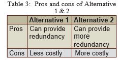
The pros and cons of Alternative 1 and 2 are indicated in Table 3.
Single EHV switchyard
The switchyard will comprise of line bays, bus bays and trafo bays. The transformer selection can be either 2 x 100% or 3 x 50%. The distribution voltage will be either 11kV or 33kV based on the consumer loads and SERC norms. For a combination of 11kV and 33kV consumers the primary distribution will be 33kV and secondary distribution will be 11kV. For secondary distribution 33/11kV substation will considered. The 33/11kV substation can either be location within the EHV substation or can be distributed as per the load centres.
Two EHV switchyard
In case Two Switchyards are considered, the configuration of the Switchyards can be same as described in the single switchyard option. Further 33/11kV distribution shall also be similar to that indicated in single EHV switchyard option. An EHV tie may be laid between the two EHV substations for further redundancy.
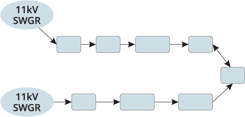
HV power distribution network
33kV and 11kV distribution
The 33KV distribution can be either a radial or a ring network. The cabling can be either directly buried or in trenches. If cabling is planned in cable tunnels then adequate provisions for fire detection, lighting, ventilation, fire barrier etc shall be considered as per statutory requirements. A typical ring network is indicated in Figure 3.
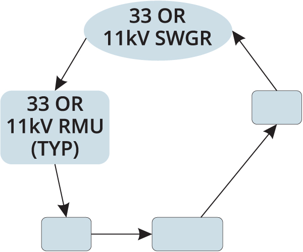
Figure 3: Ring network
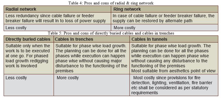
The pros and cons of radial and ring network are indicated in Table 4 and pros and cons of different types of cabling system are indicated in Table 5.
The 11kV distribution can either be radial or ring network or in case of multiple 33/11kV substations option the 11kV distribution can be in a mesh (tie) option. The mesh option will be cheaper than ring option.
The HT supply to the consumer premises shall be supplied/ tapped from the nearest RMU for radial, ring or tie feeders or shall be directly terminated at the consumer’s point of supply breaker in case of a dedicated feeder. A common RMU with adequate number of outgoing feeders can be considered for two or three plots based on availability of necessary number of outgoings and site suitability.
Power Supply for Common Utilities
Intermediate substations for common infra works i.e. outdoor lighting, water supply, solid waste management shall be planned. These substations shall be tapped from the nearest existing ring or tie network. Suitable tariff metering arrangement shall be considered for energy accounting. The LT supply shall be derived from these substations with adequate capacity of transformer. Suitable DG back-up will be considered if required depending upon the criticality of the utility.
Smart Features of Electrical System
Following features shall be considered for the electrical equipment/system:
- All revenue metering shall be through Smart Meter and Advanced Metering Infrastructure (AMI).
- All meters of EHV switchyard and in 33 and 11 KV switchgear shall be with communication ports for SCADA connectivity.
- All relays in EHV switchyard and in 33 and 11 KV switchgear shall be numerical type and suitable for SCADA connectivity.
- All operating equipment like breakers, Isolators, RMU and CSS equipment shall be suitable for SCADA connectivity.