
Recently there was heavy cyclone in Rajasthan and due to that a 400kV Transmission line got intercepted (Fig. 1). Also, many transformers failed due to line to earth, line to line faults of higher magnitude travels to the connected loads, which were beyond anybody’s control. But probably with good quality maintenance this accident could have been avoided.
We have come across the failure of transformers due to not monitoring their proper storage – particularly nitrogen filled. The transformer was kept idle for a long period without monitoring the presence of N2 in the Job. Due to poor quality of gaskets, sometimes minor leakages are observed, and that become the source of N2 escape – and that is slowly replaced by atmospheric air, which ultimately deteriorates the insulation of the job – and tends to fail when electric supply is given.
![]()
Figure 1
Winding and electrical circuit failure observed due to improper clearance, insulation of winding aged due to continuous over loading, insulation got damaged but not noticed/ overlooked, during winding of coil transposition (Fig. 2) are not made proper and got sharp edges due to improper bending tool used, joints of conductors are not made proper resulted overheating, inter-strand (Fig. 3) insulation is inadequate to carry voltage safely and ultimately resulting circulating current to flow and to overheat the point of fault. Inter turn failure is more severe and can lead to fire the Job and sometimes due to enormous force caused due to fault gases Tank can be busted. Static end rings are provided at the ends of winding for capacitance distribution but sometime the gap between starting & finishing is not provided / insufficient resulted heavy current flow and ultimately burnt. If the process of the Job is not carried out under control atmosphere / dust free chamber, there is every possibility of foreign particles / metallic dust entering in the coil and create conductive path to make inter-turn/ inter tapping leads short and fail the Job. Therefore, Partial Discharge test is essential to detect presence of such particle well before the failure occurs.
![]()
Figure 2
Optimum transposition of parallel conductors
![]()
Figure 3A

Figure 3B
Core and clamping structure failure observed due to poor clearance and moisture effects. Some time core belts found shorted each other and resulting inter turn failure. Pressboard liner if not properly dried and used of lesser width / thickness used under the core belt it can fail due to low creep age. Recently, we have come across one failure of Fiber glass stud with tank wall due to poor clearance, so long so due to continuous pitting with Tank wall tank surface was having a hole and oil started coming out through the hole in the form of a jet.
Bushing failure due to ingress of moisture, poor Tan delta and Capacitance value, loose / bad joints of lead, low level of oil in the oil conservator, leakage in the conservator and Test cap short with body.
Electrical failure : Transient over-voltage, load current, short circuit fault current due to line to ground, line to line, line to line and to ground, lightening and switching surges.
Operating environment (Physical): Temperature (operating at full load with high ambient temperature humidity index) wind, rain, seismic and pollution.
Frequent number of operation of Tap Changer may cause poor contact or worn contact and result to failure due to unbalance current flow. Sometimes due to Earth Quake, vibration exceeds its resonance limit and result to failure. So, foundation should be shock proof to withstand / dump the vibration effect.
Moisture contents in oil is a very detrimental effect in the Transformer and resulted failure of active part / high voltage withstanding capacity. So time to time, value should be noted and should be improved to the required value – as per the voltage class of Transformer by on line Filtration method / off line as found suitable.
There is an increasing need for power utilities to use assets to their fullest while maintaining system reliability.
Transformers which have exceeded their design life or are approaching the end of their operating life, require all the more attention as compared to new transformers. Due to increasing failure of large power transformers the maintenance engineers are seriously reviewing their O&M procedures in order to prevent forced outages, incur less maintenance cost, and to have longer life of equipment. To assess the extent of deterioration within the transformer, it is necessary to employ the appropriate diagnostic tool.
A few decades ago, Tan delta / Insulation Resistance measurement of winding / bushing, monitoring of oil / winding temperature, checking of BDV of oil and fault gas analysis were framed as the major part of condition monitoring strategy. Latter on DGA & Furan analysis of oil are added and proved to be the effective tools in the condition monitoring of transformer. However, due to the advanced and improvement of technology following additional diagnostic tests have been included for condition assessment of transformer, which have saved power transformers from undergoing major damages.
- Partial Discharge Measurement.
• Sweep Frequency Response Analysis.
• Recovery Voltage Measurement.
• Thermo Vision Measurements.
• Dissolved Gas Analysis.
Partial discharge measurement
Partial discharge occurs in oil filled transformers due to the following reasons. Partial Discharge (PD) occurs when a local electric field exceeds a threshold value resulting in a partial breakdown of the surrounding medium. Its cumulative effect leads to the degradation of insulation. PDs are initiated by the presence of defects during its manufacture or the choice of higher stress dictated by design consideration. Measurement can be collected to detect these PDs and monitor the soundness of insulation. PDs manifest as sharp current pulses at transformer terminals whose nature depends on the types of insulation defects measuring circuits and detectors used.
Generally acoustic method (Fig. 4) is being used at sites since it is cheaper, simple and online measurement on the Tank, PD activity region can be identified. Acoustic PD method employs a sensor that converts sound signals into electrical pulses. Sound being emitted by partial discharge inside the transformer is picked up by the sensor, and is converted into electrical sensor which is further amplified by the main equipment neglecting false signals due to core vibration, noise produced by cooling system. The number of peaks in the signal available for one second is stored as counts per second. PD may not cause an immediate failure but definitely gives sound information of healthiness of transformer.
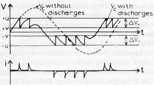
Figure 4A
PD PATTERN WHEN THE VOLTAGE APPLIED IS TWICE THE INCEPTION VOLTAGE

Figure 4B
MODEL OF A VOID-ABC DIAGRAM
- Voids in the solid insulation.
• Conducting particles in paper or in oil.
• Wet fibers in oil.
• Gas bubbles in the oil.
• Sharp edges of conductor.
Sweep frequency response analysis
When a transformer is subjected to several short circuits with high fault currents, the mechanical structure and winding are subjected to severe mechanical stresses consequently may cause deformation / displacements of windings as well as changes to winding (Fig. 5) inductance or capacitances in transformers. It may also result in insulation damage and turn to turn faults. Such small movements may not be detected through the conventional condition monitoring techniques, such as DGA, Winding resistance measurements, capacitance and tan delta measurements etc., however frequency Response measurement has proved to be an effective off-line tool to detect these changes and is widely being used world wise. The test is repeatable and immune to electromagnetic interference and is not influenced by weather.

Figure 5A
By checking or un-checking the tick box at the left of the legend name it is possible to make the trace visible on the chart or invisible. This particularly useful when comparing a number of traces simultaneously.

Figure 5B

Figure 5C
![]()
Figure 5D
![]()
Figure 5E
Following inference can be drawn from the test results and demonstrated through photographs.
- Transformer is healthy and there is no moment of windings.
• Transformer is damaged and requires immediate repairs.
• Minor winding movement is occurred but the transformer can be run under close monitoring.
• Internal inspection of transformer can be avoided after it had met heavy short/circuit inter turn faults.
Recovery Voltage Measurement (RVM)
Moisture in transformer has an adverse effect on the dielectric strength of oil and paper. It reduces mechanical strength of paper and accelerates the aging process which ultimately reduces the electrical strength and lead to failure. In addition to conventional tests viz. capacitance, tan delta and insulation resistance measurement for assessing the moisture in transformer. DC recovery voltage measurement (Fig. 6) is another off-line diagnostic tool for the condition monitoring of the oil, paper insulation of transformer. It detects the content of water (in percentage) present in insulation system.

Figure 6
Thermo vision measurement
Thermal imaging is one of the most valuable diagnostic tools used for condition monitoring of equipment. Infra red pictures (Fig.7) are produced by which temperature measurements can be made. By detecting anomalies often invisible to the naked eye, thermal imaging allows corrective action before costly system failure occurs. A thermal vision camera has proven to be an effective on-line condition monitoring tool of a transformer for determining hot spots on tanks, bushing terminal joints etc., this information is useful in predicting the temperature profiles within the inner surface of transformer tank and would provide approximate details of heating mechanism and deciding the remedial action to be taken well in advance.
Infra Red Thermal Scan Of Transfomer
![]()

Figure 7
Life extension programme of transformer in service
Some of this tips used to improve the life expectancy of transformer in service are highlighted below:
- Strictly adhere to the routine maintenance schedule, which include hourly, daily, quarterly, half yearly, yearly inspections as prescribed by the OEM.
• Transformer oil being hygroscopic absorbs moisture from the surrounding air. Oxidation and contamination of oil can be avoided by adopting proper oil preservation system. The most effective way is by using air-cell in conservator. By this technique , transformer oil does not come in contact with air directly but through oil resistant nitrile rubber membrane. Air–cell (Fig.8) can be retrofitted on old transformers also.
• Thermosyphon is an online oil filtration system (Fig. 9) having adsorbents viz activated alumina, silica gel etc., for continuously removing moisture and acid from transformer oil. This system is installed at the manufacturing stage and has proven to be very effective.
• Employing condition monitoring tools viz. DGA, Furan analysis and other online / offline tests as explained above for assessing health of transformer and accordingly deciding the maintenance strategy.
• Over the years, utility system has grown resulting in an increase in the available short circuit MVA. Transformers, which have aged and also having lower percentage impedance than required by the system, are likely to get damaged if installed in such high fault current areas. Hence, while shifting old transformers to new areas, this precaution may be kept in mind.
• Reducing the fault currents for the more frequent line to ground faults by installing neutral reactors can protect many old transformers. Also, it will be worthwhile to use metal oxide gap less surge arrestors for better protection and having higher safety margins.
• As Stray losses of transformer are generated at many places and it become extremely difficult to determine with sufficient reliability the total loss level by calculating every element individually if this losses are control by proper designing such as use of continuously transposed conductors (CTC FIG. 10) in the chase of high current winding. Life expectancy of the transformer can be largely improved.
Residual Life Assessment
Why Residual life assessment??
- Methodology
• Analysis of history of transformer
• Furan Analysis
• DP Evaluation
- Degree of polymerization:Interpreting the remnant life in the transformer based on the degree of polymerisation:


Figure 8

Cellulose degradation takes place by 3 mechanisms
- Thermal degradation
2. Oxidative degradation
3. Hydrolytic degradation - Furan Analysis:Furanic compounds are produced during the breakdown of the cellulose insulation in Transformers due to ageing and other reasons. The furanic compounds are:\
- 2-Furaldehyde (2 FAL)
• 5-Methyl-2-Furaldehyde (5M2F)
• 5-Hydroxymethyl- 2-Furaldehyde (5H2F)
• 2-Acetyl furan (2ACF)
• 2-Furfuryl alcohol ( 2FOL)
Studies have indicated that there is a relationship between the 2 FAL and the DP.
Generally from a practical point, it is difficult to obtain proper sample of the paper for evaluation of the DP. As for this the oil must be drained and a proper sample obtained and the area is to be reinsulated.

Figure 9

Figure 10

Figure 11

Figure 12
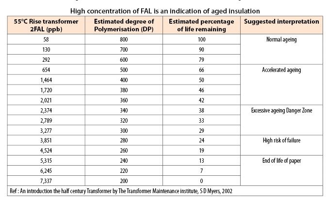
More often than not this is difficult. Hence, the method of estimation of the DP and the remnant life of the transformer by measuring the furan content of oil is very convenient.
How to enhance the life of transformer?
- Vapour Phase Drying
• Low Frequency Heating
• Overhauling by conventional method
• Overhauling by modified method
• Online dry out

If you want to share thought sor feedback then please leave a comment below.


