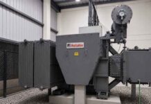

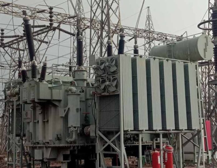
Different types of transformers find use in power sector. The most common types include:
- 1 phase transformers
- 3 phase transformers
- Auto transformers
Standard Specification
The transformer must conform to the following latest standards in vogue.
- Indian Standard; IS: 2026
- International Electrotechnical Commission Standard; IEC 60076.
- Institute of Electrical and Electronics Engineers; IEEE Std; C57.12.00
Rating
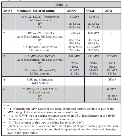
The rating of the transformers depends on the cooling System adopted for cooling the oil inside the transformer. Generally, the highest rating is achieved when the highest designated rating of the cooling system of the transformer is in operation.
Example:
- 160MVA, 220/132/33kV auto transformer: 160MVA is achieved when “ON AF” is in operation.
- 315 MVA, 400/220/33 kV autotransformer: 315 MVA is achieved when “OF AF” is in operation.
- 135 MVA,240/11kV GSU transformer in Hydel power Stations: Since these transformers have OFWF cooling. They have only one rating.
Cooling System
The cooling system is defined with an abbreviation of 4 alphabets. First 2 alphabets denote the oil cooling and the following 2 alphabets denote the status of the air /water for cooling.
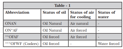
- *AF: Such cooling arrangements are used where the radiators are mounted directly on the body of the transformer tank and also separately mounted structure/pedestal support. Cooling of the hot oil takes place while it is passing through the radiators and cooling fans mounted on these force the air on to the radiators.
- **OFAF: In such cooling arrangements the bank of radiators are externally mounted on structure/ pedestal equipped with adequate no. of cooling fans. The radiators are connected to the tank through top and bottom headers. The suitable in-line type oil cooling pumps are connected at the outlet of the bottom headers in the cooling pipe work at the oil in let end of the tank .The cooled oil through the radiator banks is forced into the transformer tank through the pumps.
- ***OFWF (Coolers) also known as ‘Oil to Water Heat exchanger’: This type of cooling arrangement is generally provided where water is available in abundance, particularly in Hydel Power Stations. There it is a general practice to provide 2×100% OFWF coolers (that includes one 100% standby). The oil pressure is more than the water pressure. The standby cooler can be taken over in service by operation of / regulating certain valves with either of the pumps. The operation of such cooling arrangement is kept in service for 24×7.
Typical Transformer Ratings
Typical sample ratings mentioned hereunder are the standard ratings as specified in CBIP Manual no. 317 at frequency of 50Hz.
Vector Group
This shows the winding configuration of a transformer.
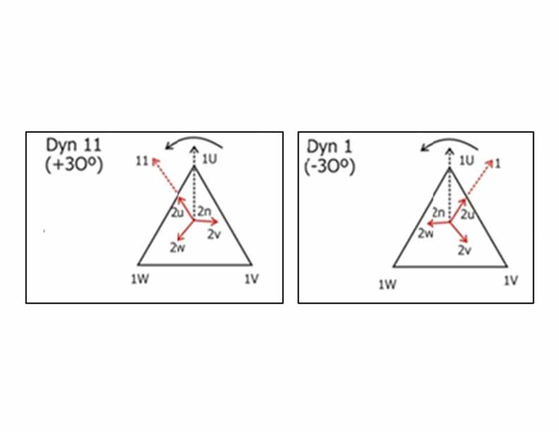
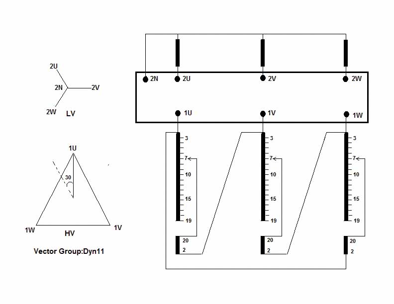
- Dyn11-HV: This winding is connected in delta formation whereas LV winding is in star formation with neutral with 30O lead from the HV winding Voltage vector; 11 indicates 11-O’ clock position on the clock dial with respect to12 O’ clock. Each 5 min graduation on the clock with respect to each other is of 30O apart. (Fig.-1)
- Dyn1-HV: This winding is connected in delta formation whereas LV winding is in star formation with neutral, with 30O lag from the HV winding Voltage vector 1 indicates 1-O’ clock position on the clock dial with respect to 12 O’clock. Each 5 min graduation on the clock face with respect to each other I 30O apart. (Fig.-2).
- YNyn0: This means that there is no phase shift between HV and LV voltages. Both the windings are Y N Means-Star connected HV winding with HV Neutral and YN means- LV winding too is star connected with neutral. (Fig.-3).

- YNa0d11: Auto transformers have vector group depicted as-YNa0d11. Here ‘a’ stands for Auto connection. HV and IV have 0O phase displacement between them having common neutral – HV neutral N. There is a phase displacement of 30O between HV and LV voltage vectors. The LV voltage vector leads HV by 30O. (Fig.- 4).
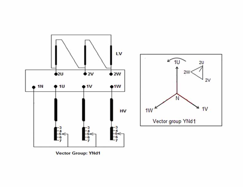
- YNd1 or YNd11:The GSU (Generator Step Up) Transformers are generally of YNd1 group, however, in some Generating Utilities YNd11 are also used. (Fig.-5)

Note: It may be noticed that while representing the vector group of any Transformer, the vector representation should be HV vector first then the LV vector. This is generally the case with the GSU (Generator Step-Up) Transformers. The terminal voltage of any generator is in LV Delta only.
Example: Normally, 200MW Thermal Power Generator has the terminal voltage of 15.75 kV (Delta). The GSU of this is 250 MVA, 240/15.75kV, which is used to connect the 220kV supply to the Grid network. The vector group thereof is YNd1.
Insulation Levels
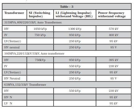
The insulation levels of the windings are mentioned in power frequency and BIL (Basic Insulation Level, which is Lightning Impulse withstand voltage, applicable as per IS: 2026 (part-3)/IEC 60076 -3.
Typical insulation levels:
- 315MVA, 400/220/33kV, Auto Transformer
- 160 MVA, 220/132/33kV Auto Transformer.
- 63MVA, 132/33kV Transformer.
BIL of Bushings
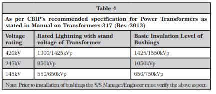
Though it is not a part of the R&D plate but it is essential to note the BIL of bushings. It has been stipulated in the CBIP manual no.317 on Transformers that the BIL of Bushing should be one level above the BIL of the Transformers.
Impedance and Significance of % Impedance Volts
Definition: The percentage impedance of a transformer is the volt drop in terminal voltage on full load due to the winding resistance and leakage reactance expressed as a percentage of the rated voltage.
Impedance volts in% at rated MVA base: It is the % of the rated HV terminal voltage required for circulating the full load current, keeping all the 3 LV terminals shorted.
Example: Say, full load current flows from the source if 13.86 kV voltage applied to the HV side (132kV) keeping the LV (33kV) side short circuited of a say 40 MVA 132/33kV Transformer.
%Z=13.86/132 x100 = 10.5%
On the R&D plate, it is designated as %Impedance volts at base MVA.
Isc = Ifl/(%Z) x 100.A = Ifl x (100/(%Z)).A,
Where Ifl = Full load current and Isc = Short Circuit current
Say full load current of a 132kV side of 20MVA, 132/33kV Transformer is 87.5 A, and the % impedance volts is say 10.5%.
Therefore,
ISc= 87.5x 100/10.5 = 833.33 A on HV side and Isc on LV side = 3333.32 A.
Note: % Impedance volts of individual transformer varies as per its winding configuration (resistance and leakage reactance), therefore its true value obtained after the transformer’s complete assembly and testing at OEM’s works is inscribed/engraved on the R&D plate indicating the % Impedance volts at base MVA.
Temperature Rise
- Top Oil Temperaturerise: 45OC, means the oil temp of Transformer can rise up to 45OC max above the ambient temp.
- Mean Winding Temp rise: 50OC, means the winding temp of Transformer can rise to 50OC max above the ambient temp.
Guaranteed Losses
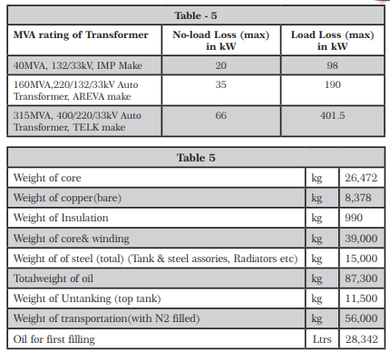
Typical guaranteed “No Load loss and Load loss” are defined by the purchaser. The transformers are designed and manufactured accordingly. Actual measured losses should be within the defined max losses and should be engraved on the R&D plate of the transformer.
Other Details
Sample: This pertains to160MVA 220/132/33kV Autotransformer of BBL make.
Tap Changers
- OLTC (On line Tap Changer): It is generally used in EHV Transformers.
- OCTC (Off Circuit Tap Changer): It is generally used in GSU (Generator Step Up) Transformers
OLTC: As the name signifies, it is an equipment, which is very essential for raising / lowering of transformer-taps so as to maintain the voltage profile on load of the system.
Type of OLTCs: Handling of the same as compared to LV winding is easy and due to the fact that it performs its duty in a lower current side of the transformer, i.e., the HV side.
Placement of the OLTC in Y connected transformer: In a 2-winding transformer, the tapchanger is generally placed close to the starpoint of the 3 phases, which is subsequently formed into the neutral point and in practice is the said neutral is grounded. The potential near the star point is very low.
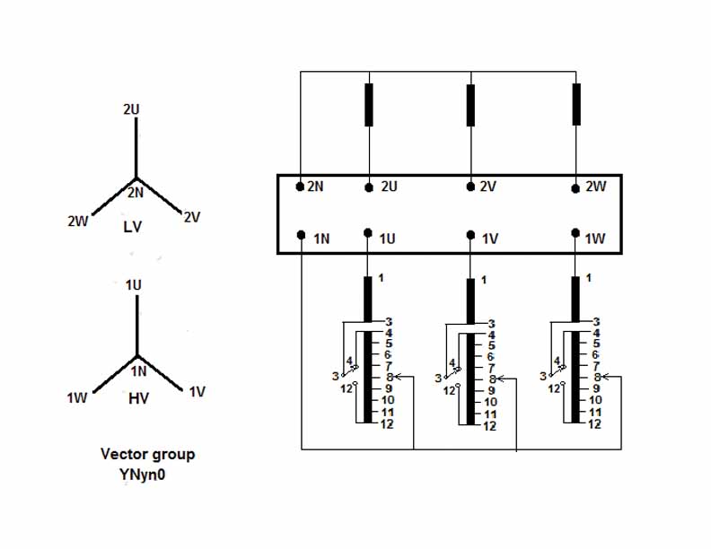
Placement of Tap winding in Dyn11 Transformer HV Delta side:
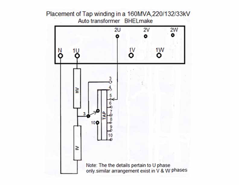
Location of OLTC in an auto-transformer: In the auto –transformer unlike the 2-winding transformer, there is no separate winding for IV (intermediate voltage), as it is called.
This Transformer also has LV winding in Delta-called as tertiary winding. The taps are selected from tap winding, which is separately provided between the HV and IV windings (fig.-8)
As a practical example: The tap connection of 220/132/33kV, 160 MVA 3 – Ph Auto-Transformer, BHEL-make is shown in figure no-8. There are as many as 13-taps with single reversing changeover selector switch.
OCTC (Off Circuit Tap Changer): It can be seen from the fig 9, that, since it is a YNd1 GSU transformer, the tap winding is at the neutral only. There are only 5 no taps. Tap no 3 is the Normal tap with variation of 2.5%. This is of a GSU Transformer 250 MVA, 240/15.75kV TELK make transformer.
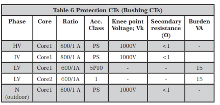
CTs: Following are the CT ratios and accuracy class, knee point voltage& VA burden etc used of a 160 MVA 220/132/33 kV YNa0d11 auto transformer as specimen.
Protection CTs: These ring type CTs are placed encircling the Bushing in the turrets. The CTs are bushing CTs and the outdoor mounted Neutral CT of PS class of used for REF(Restricted Earth Fault) protection. In an auto transformer HV & IV winding being YNaod11 vector group, have one neutral only.
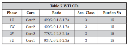
WTI- CTs: They are ring type CTs Winding temperatures applications of different windings.
Oil Preservation Systems
Conventional conservator: This system is common in Smaller Transformers /Sub Transmission Transformers where the air space above the oil level is vented through a de-humidifier unit known as silica gel breather. The transformer breaths the atmospheric air through it when the oil cools down during night hours or when the load is reduced during off peak hours. If proper monitoring of condition of silica-gel breather is not done, there is every possibility of moisture entering the transformer.
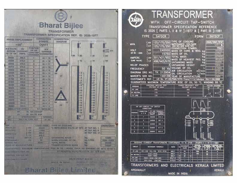
250 MVA, 240/15.75 kV GSU Transformer, TELK make
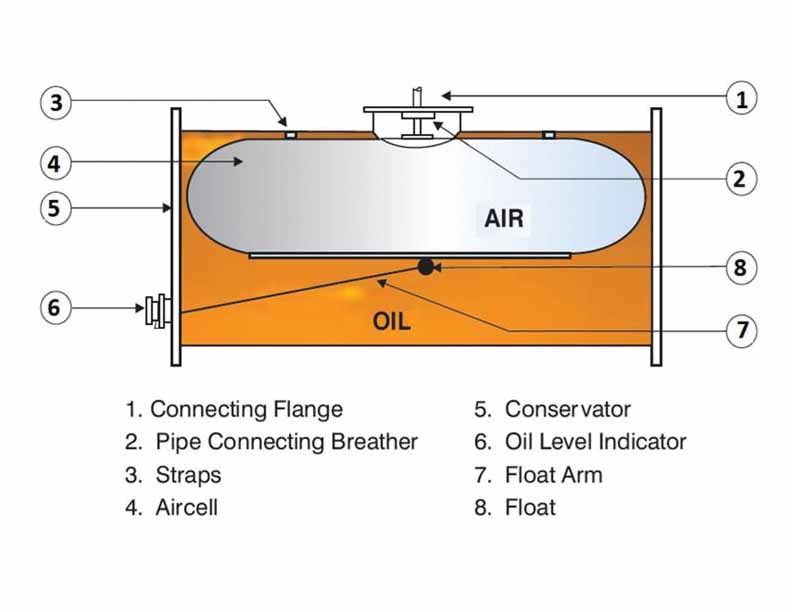
Air-cell conservator: It is almost two decades since this oil preservation system came into practice. This prevents possibility of transformer oil coming in contact with the external breathing air. In this system, an Air-cell (a synthetic rubber bag) occupies the space above the oil. The interior of the bag is then connected to the atmosphere – so it can breathe in air when the transformer cools down and oil volume is reduced and breath out when the transformer heats up. (fig.-10) OEM’s instructions should be strictly followed for installation & commissioning of this system.

K.K. Murty is B.E. (Hons) Elec. Engg, FIE (India) & CE (India), Member-CIGRE’ India. He was the former Chief Engineer & HOD (Testing & Commun.), M.P. Power Transmission Co. Ltd. Jabalpur.