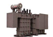

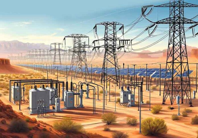
The modern world runs on electricity, but the journey from a remote power plant to the outlet in your wall is a feat of engineering physics. At the center of this journey sits the power transformer. Without it, our electrical grid would be incredibly inefficient, dangerous, and likely localized to within a few miles of a generator.
Types of Power Transformers
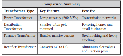
To understand the diverse world of power transformers, we have to look at how they are categorized. They aren’t ‘one size fits all’; a transformer used at a nuclear power plant is a completely different beast than the one sitting on a pole in a suburban neighborhood.
They are generally categorized by voltage level, insulation medium, and specific application.
Classification by Voltage Level
This is the most common way to distinguish transformers in the utility sector.
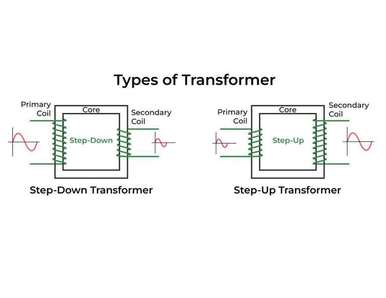
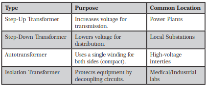
Step-Up Transformers
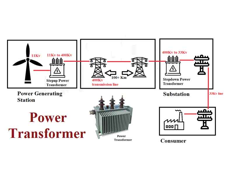
These are found at generating stations (thermal, hydro, or nuclear). They take the relatively low voltage produced by the generator (usually 11kV to 25 kV) and ‘step that up’ to extremely high voltages (up to 765 kV) for long-distance transmission.
- Primary Use: Minimizing I2R energy losses during cross-country power transport.
Step-Down Transformers
Located at the receiving end of the transmission lines (substations), these convert high-voltage electricity back down to lower levels (66 kV, 33 kV, or 11kV) for safe distribution within a city.
- Primary Use: Preparing electricity for local distribution and industrial consumption.
Classification by Insulation/Cooling Medium
How a transformer breathes and stays cool determines where it can be placed.
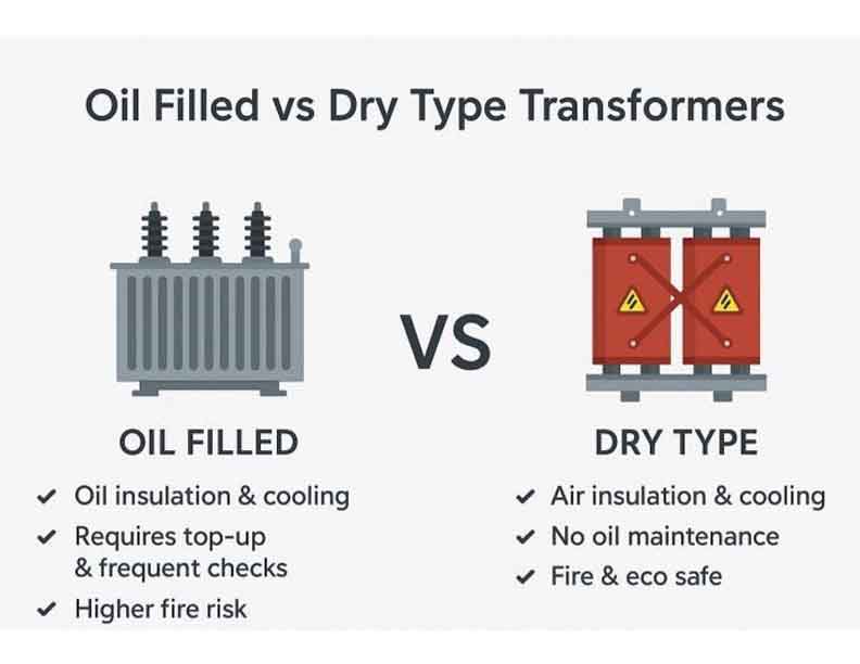
Oil-Immersed Transformers
The core and coils are submerged in a tank of mineral oil. The oil serves two purposes: it’s an incredible electrical insulator and a highly efficient heat conductor.
- Uses: Outdoor substations, high-voltage transmission, and large-scale industrial plants.
- Pros: High cooling efficiency and long lifespan.
Dry-Type Transformers
Instead of oil, these use air or cast resin for insulation. Because they don’t contain flammable liquids, they are much safer for indoor use.
- Uses: Hospitals, shopping malls, underground mines, and high-rise buildings.
- Pros: Fire-safe, low maintenance, and environmentally friendly (no oil leaks).
Specialized Transformers and Their Uses
Autotransformers
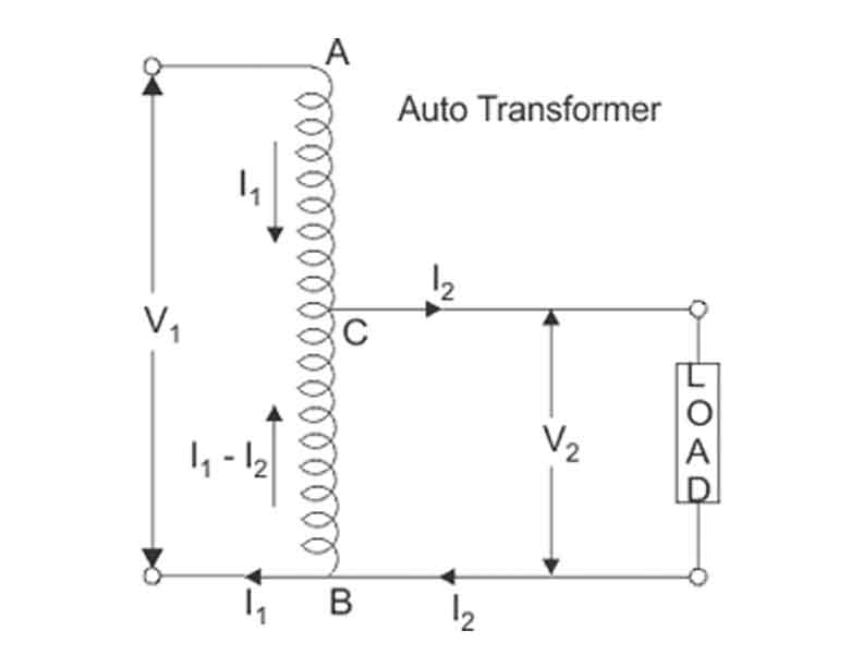
Unlike a standard transformer with two distinct windings, an autotransformer has a single winding that acts as both primary and secondary. They are smaller, lighter, and cheaper but lack electrical isolation.
- Use Case: Connecting two different transmission voltage grids (e.g., 230 kV to 115 kV) where isolation isn’t required.
Instrument Transformers
These are ‘miniature’ precision transformers used for monitoring the grid rather than moving bulk power.
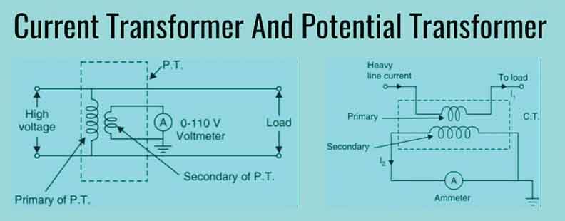
- Current Transformers (CT): Step down high currents to a measurable level (usually 1A or 5 A) for meters.
- Potential Transformers (PT): Step down high voltages for protective relays and billing meters.
Isolation Transformers
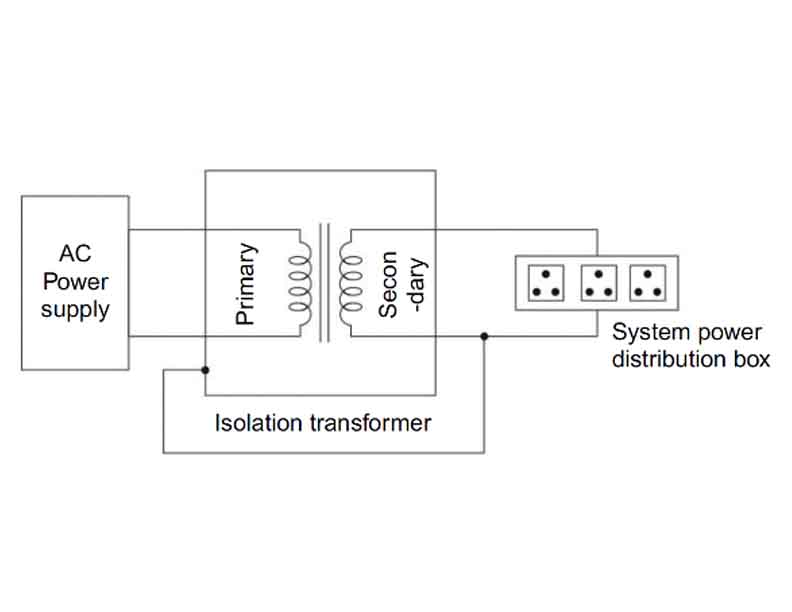
These have a 1:1 turn ratio, meaning the voltage doesn’t change. Their purpose is to physically decouple two circuits to prevent ‘noise’ or dangerous DC currents from passing through.
- Use Case: Sensitive medical equipment (like MRI machines) and high-end audio recording studios.
Phase-Shifting Transformers (PST)
In complex grids where power flows through multiple parallel paths, a PST allows operators to ‘push’ or ‘pull’ power along specific lines.
- Use Case: Managing grid congestion and preventing certain transmission lines from becoming overloaded while others sit idle.
The Fundamental Purpose
A power transformer is a static device that transfers electrical energy between two or more circuits through electromagnetic induction. Its primary job is to change the voltage levels:
- Step-up: Increasing voltage for efficient long-distance transmission.
- Step-down: Decreasing voltage to safe, usable levels for homes and factories.
Why do we need high voltage?
- The reason is simple: efficiency. When electricity travels through a wire, some energy is lost as heat due to resistance. This loss is calculated by the formula:
Ploss = I2R
By increasing the voltage (V), we can decrease the current (I) for the same amount of power. Since losses are proportional to the square of the current, doubling the voltage doesn’t just halve the loss – it quarters it.
Core Components and Construction
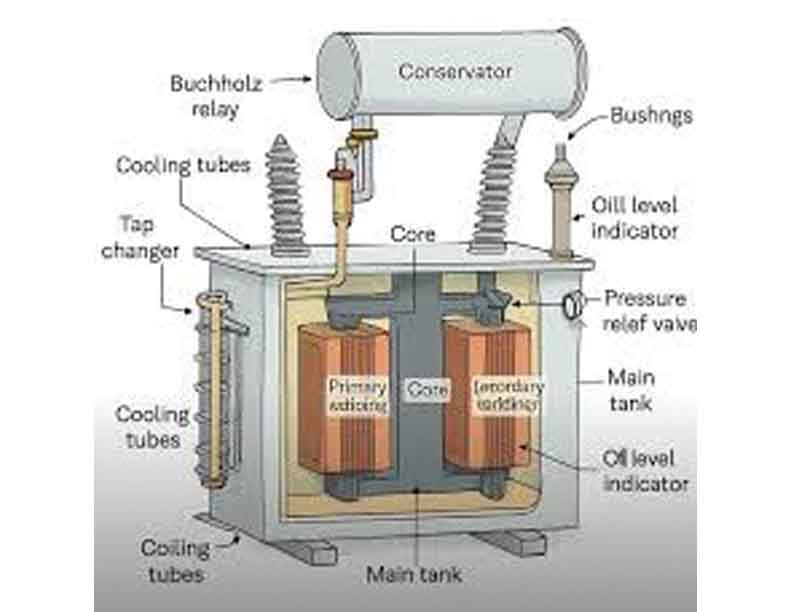
A power transformer is more than just wire and iron. It is a highly engineered system designed to withstand extreme thermal and mechanical stress.
The Magnetic Core
The core provides a low-reluctance path for the magnetic flux. It is typically made of Cold-Rolled Grain-Oriented (CRGO) silicon steel.
- Laminations: To prevent energy loss from ‘eddy currents’, the core isn’t a solid block. It is made of thin sheets (laminations) insulated from each other.
Windings
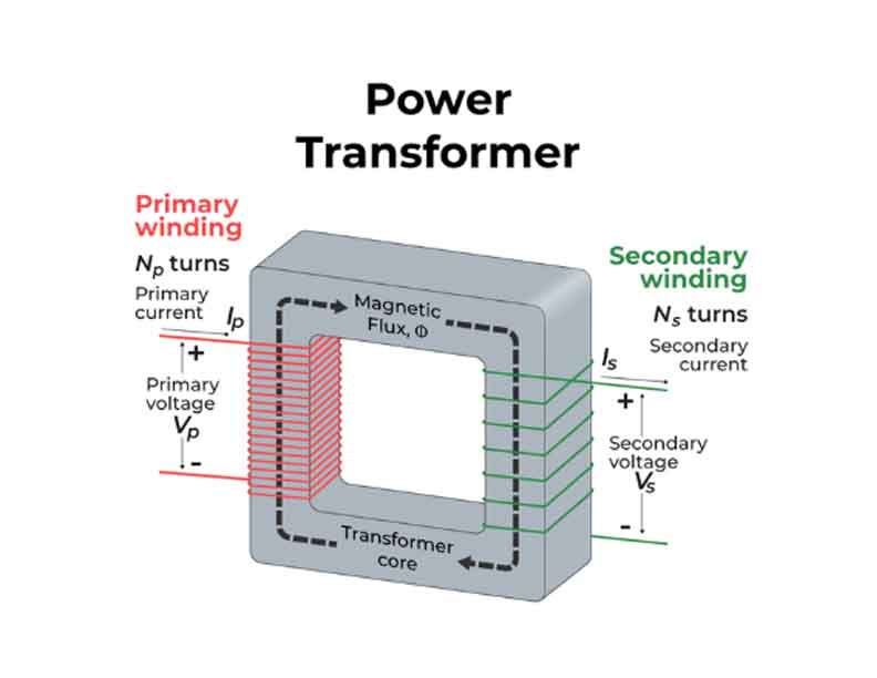
These are the coils of high-conductivity copper or aluminium.
- Primary Winding: Connected to the input source.
- Secondary Winding: Connected to the load.
- Insulation: Windings are wrapped in specialized paper or synthetic materials and submerged in oil to prevent short circuits.
The Cooling System
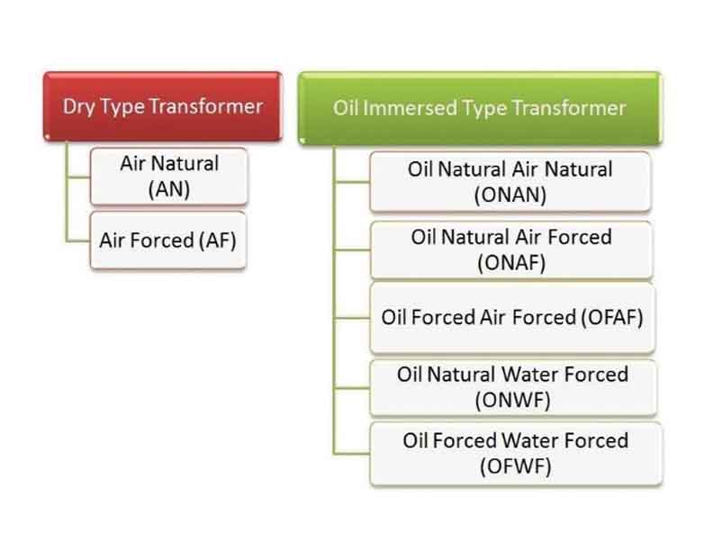
Power transformers generate immense heat. To prevent the insulation from melting, they use:
- Transformer Oil: Acts as both an insulator and a coolant.
- Radiators and Fans: Large external fins that dissipate heat into the air.
- Conservator Tank: A small tank on top that allows the oil to expand and contract as it heats up.
How it Works: The Physics
The operation is based on Faraday’s Law of Electromagnetic Induction. When an Alternating Current (AC) flows through the primary coil, it creates a fluctuating magnetic field in the core. This field ‘links’ with the secondary coil, inducing a voltage.
The relationship between the number of turns (N) and the voltage (V) is defined by the Turn Ratio:
Vp/Vs = Np/Ns
To truly understand the ‘magic’ of how these massive machines work, we need to look at the math of efficiency and the physical forces at play. While an ideal transformer would be 100% efficient, real-world units face several types of energy ‘leakage’.
The Mathematical Framework of Efficiency
Efficiency (h) is the ratio of output power to input power. In a power transformer, it is expressed as:
h= Pout /(Pout + Plosses) x 100%
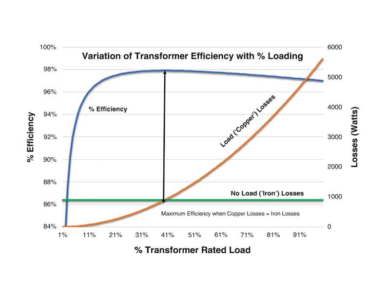
Power transformers are among the most efficient machines ever created, often exceeding 98% to 99% efficiency. However, because they handle megawatts of power, even a 1% loss represents a massive amount of heat that must be managed.
The Two Pillars of Loss
To calculate efficiency, engineers categorize losses into two main groups:
- Core Losses (Iron Losses): These occur in the magnetic core and are constant regardless of the load. They consist of:
– Hysteresis Loss: Energy spent in reorienting the magnetic domains in the steel every time the AC cycle flips.
– Eddy Current Loss: Small ‘whirlpools’ of current induced in the core itself.
- Copper Losses (Variable Losses): These occur in the windings due to electrical resistance. They increase with the square of the current (I2R).
To be continued…

Reshmi Goppi is an Electrical Engineer with PGDM (Executive) in Operations Management from IMT CDL, Ghaziabad. She has 18 years of working experience in Power Sector in large scale Substations and Transmission projects – domestic as well as international. Being a career counsellor, writer and guest speaker, she is connected to many forums.