
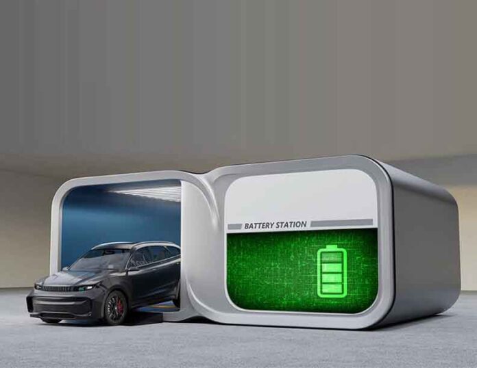
Battery Swapping Station (BSS) provides a practical pathway for large-scale electric vehicle adoption by ensuring continuous and reliable energy access. Compared with conventional charging stations, BSS offers greater operational flexibility and improved economic viability for operators and local communities.
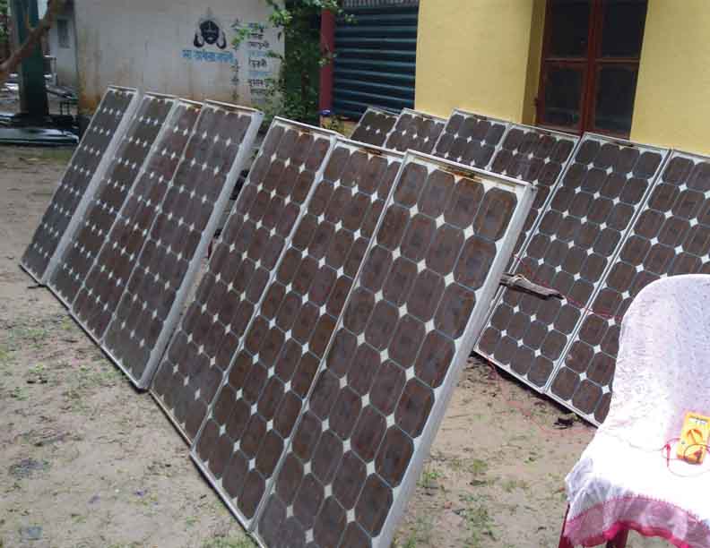
In this system, batteries are charged using both DC and AC power, including solar energy. Solar-generated DC power is used for daytime charging, while an inverter supplies AC power from stored energy after sunset, enabling uninterrupted 24-hour operation.
Fully charged batteries are stored at the station and exchanged for depleted ones in Battery-operated Small Vehicles (BoSVs) by trained personnel, while additional battery packs can be obtained for longer trips, significantly reducing vehicle downtime. When BSS facilities are directly connected to the local distribution grid, problems such as harmonics, voltage instability, poor power factor, and increased losses may occur. These issues are avoided in the proposed off-grid solar-powered system, which operates independently of the utility network and therefore does not affect grid performance.
To further enhance charging efficiency, the system integrates an Energy Recovery Cell (ERC) with an LLC resonant converter. This configuration recycles rectifier ripple energy back to the DC bus, reducing switching losses through zero-voltage switching and improving overall efficiency. Although earlier designs reduced charging time from eight to four hours, this was still unsuitable for rural EV operators due to prolonged vehicle inactivity and associated economic losses. By combining a solar-powered fast charger with BSS deployment in rural Bengal, the proposed approach reduces effective EV downtime to nearly ten minutes, offering a highly efficient and practical alternative to conventional charging.
Resonant LLC Converter: Structure and Functionality
The resonant converter serves as a critical component in the system, composed of an inductor (Lr) and a capacitor (Cr) that together form the resonant tank circuit. This circuit is designed to enable efficient energy transfer to the load via a transformer. By facilitating smooth current flow within the circuit, the resonant tank enhances stability and performance.
The system begins by converting the DC input into a square wave through a switching bridge network. This network uses a full-bridge design, employing four Metal-Oxide-Semiconductor Field-Effect Transistors (MOSFETs) to efficiently produce the square wave signal. The square wave is then passed through the resonant LLC tank, which acts as a harmonic filter. The primary purpose of the resonant LLC tank is to remove unwanted harmonics from the square wave signal, delivering nearly sinusoidal voltage and current.
The LLC resonant converter is distinguished by its high efficiency and reduced switching losses, achieved through the implementation of Zero Voltage Switching (ZVS). The technique ZVS ensures that switching transitions occur when the voltage across the switch is zero, significantly minimizing energy losses.
By integrating the resonant converter, switching bridge network, and transformer, the system achieves an efficient DC-to-AC conversion process. The resonant LLC tank not only filters harmonics but also generates high-quality AC signals. The transformer ensures both voltage adjustment and electrical isolation, making the system safer and more reliable. This architecture is well-suited for applications that demand efficient power conversion, such as renewable energy systems, industrial equipment, and high-power electronic devices.
The Rectifier Stage in the LLC Resonant Converter
The rectifier stage in the LLC resonant converter utilizes a full-bridge diode configuration to convert the high-frequency AC signal from the transformer into a unidirectional DC voltage. This arrangement comprises four diodes (D1, D2, D3, and D4), strategically connected to handle both positive and negative half-cycles of the AC waveform.
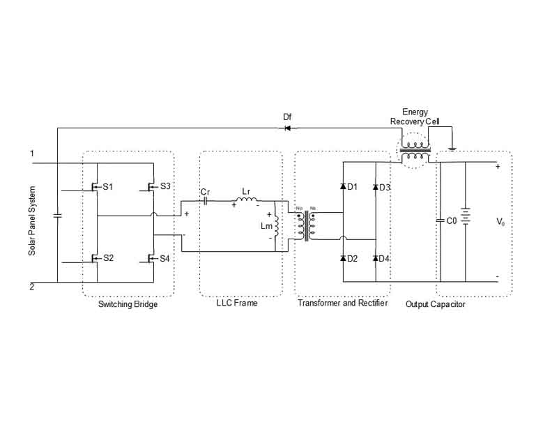
The rectifier thus converts the bipolar AC waveform into a pulsating DC output, which contains significant ripple components that require further filtering. Output Capacitor (Co) Functionality. The output capacitor (Co) is positioned downstream of the rectifier to smooth the pulsating DC signal into a stable DC output voltage. The capacitor plays two key roles, that is, Ripple Filtering and Load Stabilization.
Zero Voltage Switching (ZVS) Technique
ZVS represents a significant advancement in the domain of power electronics, aimed at minimizing energy losses during the switching processes. This innovative technique ensures that switching devices, such as Metal-Oxide-Semiconductor Field-Effect Transistors (MOSFETs), are activated precisely when the voltage across them approaches zero. Through precise timing and synchronization ZVS effectively mitigates power dissipation during switching events, a prevalent drawback in conventional hard-switching methodologies.
The principle of ZVS operation relies on the synchronization of the MOSFET’s activation with the instant at which the voltage across its terminals naturally falls to zero. This phenomenon is realized through the exploitation of circuit resonance, particularly in LLC resonant converters. These converters employ a resonant tank, typically comprising an inductor (Lr) and a capacitor (Cr), to generate oscillatory waveforms. The resonance induced by the tank circuit ensures periodic fluctuations in the voltage across the MOSFET, facilitating moments where the voltage reaches zero. The switching mechanism is strategically triggered during these intervals, thereby minimizing energy losses and enhancing system efficiency.
Energy Recovery Cell in LLC Resonant Converters
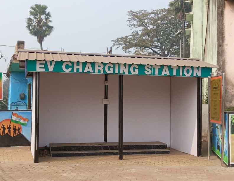
The Energy Recovery Cell (ERC), as an integral component in LLC resonant converters, plays a pivotal role in enhancing energy efficiency by recovering and reutilizing energy that would otherwise be dissipated as losses. This feature is particularly critical in high-power conversion systems, where energy wastage can significantly impact performance and operational reliability. Fig. 2 shows the hardware experimental set up of the proposed prototype system.
Battery Swapping Station
The operation of battery swapping station follows certain rules. The BSS should be stocked with sufficient numbers of fully charged battery, such that it can replace the newly entered discharged vehicles at any random time instant.
Initially, each EV drives the required power from its fully charged battery pack. Once the battery gets depleted after providing service for the expected time span, it is queued in the charging section of BSS. The batteries under charge get ready to serve the new entries of discharged EVs. Although the depleted batteries of a candidate discharged EV can be immediately replaced by freshly charged battery, the momentary charging of the fully discharged battery is not practically feasible as it requires considerable time as discussed earlier. This is the actual hindrance in deployment of EV in mostly rural as well as urban areas. This necessitated the researcher to look for a practical and economically viable solution of reducing battery charging time.
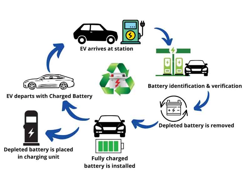
To avoid the out-of-stock scenario, the stock of the charged battery in any BSS should be greater than the numbers of entry of candidate discharged vehicles at any random time frame. The fully depleted batteries during charging time interval can also be employed in energy management system. Charge scheduling of the batteries are executed in such a fashion that they can be incorporated as a source to inject power to the electric microgrid during peak load period. For sound operation of BSS, a robust communication interface is critical between information system, EV and the BSS.
Usually wave communication establishes the bidirectional link between vehicles and information system. The information system accumulates the current location of the incoming vehicle and estimates their expected time of arrival. Thus, information is shared with the BSS through local internet. Station prepared the new charged batteries to be added to the newly entered depleted EV. As the vehicle reaches the BDS, the depleted battery specification undergoes verification and then the vehicles are allowed to swap the battery. With aid of a robotic arm the battery replacement procedure is executed without delay. An accurate record of the user’s payment, battery details, charge level, next probable scheduled charging time are stored in the cloud system for ease of tracking system. Mobile App can help the EV user to track the nearest BSS, raise requests etc.
At the peak load condition, the charging batteries are utilized as an alternative power source to inject power to the grid. This generates additional revenue. For congestion-free operation of BSS, First In First Out (FIFO) service is employed.
Battery swapping Small Electric Vehicles Charging Stations provide a quick and convenient way to recharge FLA batteries. Here’s a general overview of the working method of a typical battery swapping charging station:
- Battery Collection and Storage: The charging station has a designated area where fully charged batteries are stored. These batteries are typically pre-charged and ready for use.
- Vehicle Arrival: When Battery Operated Small Vehicles arrive at the charging station, it needs to be prepared for the battery swapping process. The vehicle is positioned over a dedicated bay or platform, and the driver may need to follow instructions displayed on a screen or communicated through an app.
- Battery Removal: The station’s automated system, controlled by man power initiates the battery removal process. The system locates the battery compartment of the EV and removes the depleted battery from the vehicle. This can involve the use of specialized tools or mechanisms to disengage and extract the battery safely.
- Battery Inspection: Once the depleted battery is removed, it undergoes a quick inspection to ensure it meets safety standards and is suitable for reuse. This inspection may include checking for any physical damage, leaks, or other potential issues that could affect performance or safety.
- Battery Swapping: If the battery passes inspection, it is then replaced with a fully charged battery from the storage area. The automated system aligns the new battery with the vehicle’s battery compartment and securely attaches it, ensuring proper electrical connections are made.
- Battery Integration: After the new FLA type lead acid battery is installed, the station’s system may perform a quick verification process to ensure the battery is properly integrated with the vehicle’s power management system. This step helps ensure compatibility and functionality between the battery and the EV.
- Battery Return and Storage: The depleted battery, which was removed from the BoSV, is stored separately in designated areas for further processing. These batteries may be sent for recharging or undergo maintenance and repair according to their current condition, depending on the station’s practices.
- Payment and Exit: Once the battery swapping process is complete, the BoSV operator can proceed to payment. Payment can be made through various methods, such as credit card, mobile payment apps, or an account linked to the charging station service. Once payment is confirmed, the driver receives a receipt or notification, and they can safely exit the charging station.
BoSVs, are built from several essential components. The chassis forms the main structural frame, providing strength, stability, and support for all other parts. Propulsion is provided by a 48 V, 1000 W brushless DC (BLDC) motor, which converts electrical energy into mechanical motion and may be wheel-mounted depending on the design.
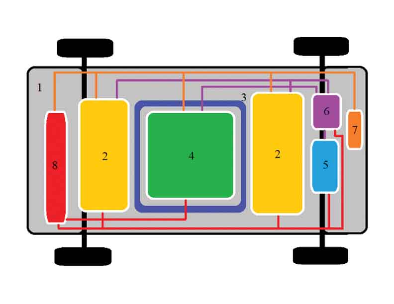
1: BoSV podium, 2: integrated batteries, 3: altercation aperture, 4: interchangeable supplementary battery pack, 5: Brass less DC (BLDC) motor, 6: power supply unit with electronics devices, 7: control system unit, 8: cooling arrangement.
Electrical energy is stored in a battery pack typically made up of flooded lead-acid batteries rated at 12 V and 100 Ah each. Four batteries are connected in series or parallel to achieve a 48 V supply suitable for driving the motor, with the battery capacity directly influencing the vehicle’s travel range.
A controller governs the electrical system by regulating power delivery from the battery to the motor, controlling speed, and responding to inputs from the throttle, brakes, and sensors. Vehicle speed and acceleration are adjusted through a handlebar-mounted throttle, while mechanical brakes are used to decelerate and stop the vehicle safely.
Conclusion
Battery-operated small electric vehicles play a vital role in transporting goods and passengers in rural India, yet they suffer from several operational limitations. This project effectively addresses these challenges by simplifying and accelerating the charging process through the use of full-bridge LLC converters, which significantly reduce charging time.
A fully off-grid, solar-powered electric vehicle charging station integrated with battery swapping technology has been developed to overcome energy and time constraints. As a result, vehicle operators no longer lose productive hours waiting for batteries to charge and can instead increase their income by using that time for transportation services. Since the system is powered entirely by solar energy, it incurs no running cost and remains completely independent of the electrical grid, eliminating any risk of grid-related issues.
Overall, the proposed solution promotes sustainable development by reducing pollution while simultaneously improving the economic condition of drivers and supporting socio-economic growth in rural communities.

Dr. Bidrohi Bhattacharjee holds a Ph.D. in Electrical Engineering from the Indian Institute of Technology (ISM), Dhanbad, India. He earned his B.E. in Electrical Engineering and M.Tech. in Illumination Technology and Design from Jadavpur University, Kolkata, West Bengal, India. Currently he is working as HoD and Assistant Professor at the Electrical Engineering Department in Budge Budge Institute of Technology, Kolkata, India. His research interests span power electronics, electric drives, renewable energy, sustainable development, electric vehicles, and battery charging technologies. He also holds several patents in the areas of power electronics, renewable energy, and electric vehicles.