

The main problem with the Self-Excited Induction Generator (SEIG) is the lack of its ability to maintain the generated voltage and frequency with any variation in its operating condition. It has been observed that generated voltage and frequency are decided by the wind speed, excitation capacitance, and load across the machine terminals of the generator. Researchers have proposed different methods for overcoming such problems.
In order to maintain constant terminal voltage of SEIG, various schemes are proposed by researchers time to time. Continuous and smooth control in terminal voltage can be obtained by using thyristor controlled variable inductor or a saturable core reactor in parallel to a fixed value capacitor at the terminals of the SEIG.This scheme is advantageous over the thyristor controlled capacitor scheme , as thyristors are protected by inductor. Controlled rectifier inverter scheme with fixed value of capacitors may also be used to obtain constant terminal voltage and frequency. It is a two stage static conversion and it may be ideal solution for the case of variable speed prime movers. A detailed literature survey indicates that the short-shunt series compensation is a very simple method to control the terminal voltage of SEIG.
On the other hand, generated frequency is also to be maintained constant under varying demand and supply conditions to provide a good quality service to the consumers. Frequency control is achieved by raising or lowering the command signal of the speed gear changer of the prime mover. Conventional approaches are also used for frequency control using PI and PID controllers. Higher settling time and large overshoots are the main drawbacks in these schemes. The most recent approach for frequency control is adaptive fuzzy control. Further frequency control can also be achieved using different control strategies based on controlling the output power. Some of the researchers proposed energy storage systems for reactive power control. In this article, GAA model is proposed to control the load voltage and frequency of a SEIG. Simulated results are compared with experimental results on two test machines. A close comparison proves the validity of proposed modeling.
Equivalent Circuit Model Of Self-Excited Induction Generator
Fig. 1 shows the equivalent circuit of SEIG. Here fixed excitation capacitor is replaced by a Static Exciter (SE), comprising of fixed capacitor in parallel with thyristor controlled inductor. Further as shown in Fig. 1, SE is supported by a capacitor in series with the load branch of SEIG.
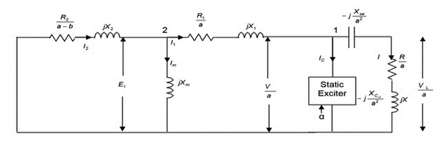
Figure 1: Per phase equivalent circuit representation of self-excited induction generator with SE & series capacitors…
Fig. 2 shows the basic scheme for SE. Here XCmin is the minimum shunt capacitive reactance for which excitation capacitance is maximum.
Assuming that the maximum shunt capacitance required under any condition is Cmax, the value of the inductor Lα can be selected as;
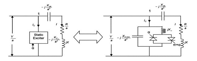
Figure 2: Basic circuit diagram of SE…
ωb Lα=1/ ωb Cmax (1)
Where ωb is base frequency in rad/sec.
The lagging current taken by the inductor can be controlled smoothly by varying the firing angle α in between 0 to 90 degrees. The fundamental component of the exciter current is given by;
![]() (2)
(2)
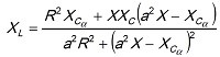
The effective value of variable capacitance provided by the SE is therefore given by;
![]() (3)
(3)
Therefore, at base frequency with α =90 degrees, Cα=Cmax,. At other frequencies, the minimum and maximum values of the effective excitation capacitance may be different. Here – jx Cα I a2 is the equivalent capacitive representation of SE for any value of α and generated frequency.
As Fig. 1 does not contain any e.m.f. or current source, therefore for successful generator operation, nodal analysis at node ‘2’ results into;
YT = 0 (4)
Total admittance, YT is written as follows;
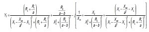 (5)
(5)
Where,
and
GA based approach i.e., GAA may be used to control the generated voltage and frequency of SEIG for any variation in its operating condition. In order to obtain the desired voltage and frequency ‘GAA’ is applied with following objective function;
OF= ![]() (6)
(6)
Where, , , 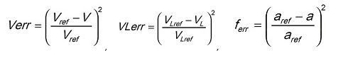
Table 1: Different cases for controlled operation of SEIG.
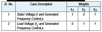
Here V, VL and a are the values of generated stator voltage, load voltage and per unit frequency while Vref , VLref and aref are the desired values of generated stator voltage, load voltage and per unit frequency of SEIG. k1, k2 and k3 are weights. Table 1 gives the values of k1, k2 and k3 for the controlled operation of SEIG. Application of GAA model with specific value of weigths i.e., k1, k2 and k3 i.e., for a particular control results in to the appropriate selection of α and Cse
Objective function as given by (6) is minimised using GAA to maintain the power quality. Bounds on firing angle, ‘o’ is 0 to 90 degrees. This approach results into a new and unique methodology to compute the values of α, series capacitance and prime mover speed simultaneously for successful controlled operation of SEIG.
Fig. 3 shows the proposed scheme to control the voltage and generated frequency of SEIG and Fig. 4 shows the flow chart for the complete control of SEIG using GAA model.
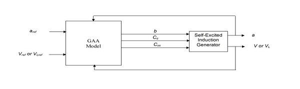
Figure 3: Voltage and generated frequency control of SEIG…
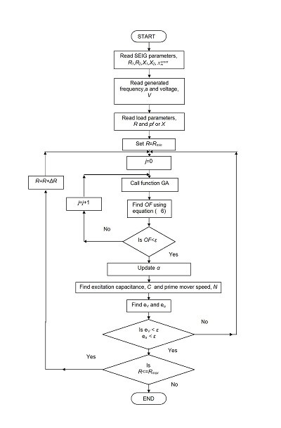
Figure 4: Flowchart of GAA using static exciter and series compensation for voltage and frequency control of SEIG…
Results And Discussions
Table 2 and Table 3 shows the comparison between simulated results using GAA model with experimental results on SEIG-I and SEIG-II (Appendix-I).
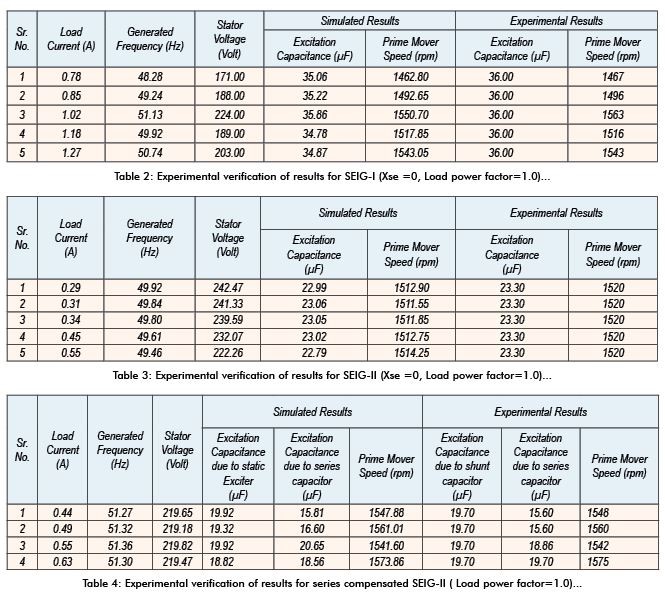
A close comparison as shown in above tables indicates the effectiveness of proposed GAA model.
Load Voltage And Frequency Control
From the consumer point of view, load voltage and generated frequency are to be maintained irrespective of operating condition of the generators. Fig. 5 to Fig. 10 shows the simulated results on SEIG-I using GAA model. After considering the proper value of k1, k2 and k3 (Table 1) in the OF as described by equation (6), load voltage and frequency are tried to maintain as rated values of machine. Unity power factor load is considered here for simulation purpose.
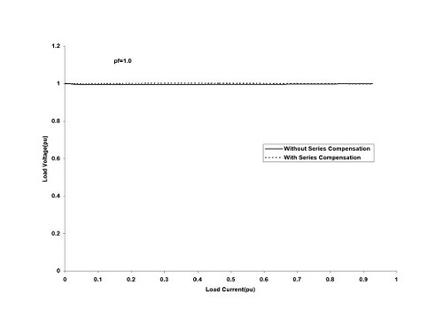
Figure 5: Variation of load voltage for ‘load voltage and generated frequency control’ of SEIG-I at unity power factor load…
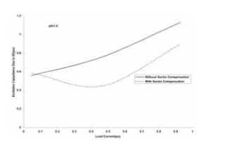
Figure 6: Variation of excitation capacitance due to SE for ‘load voltage and generated frequency control’ of SEIG-I at lagging power factor load…
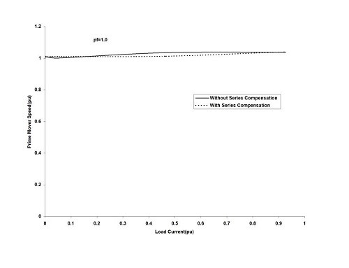
Figure 7: Variation of prime mover speed for ‘load voltage and generated frequency control’ of SEIG-I at unity power factor load…
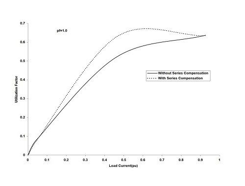
Figure 8: Variation of utilization factor for ‘load voltage and generated frequency control’ of SEIG-I at unity power factor load…
As observed from Fig. 5 and Fig. 9, a complete control is possible using GAA model. Stator voltage and generated frequency remains constant irrespective of load on the generator.
For this control, the excitation and operating speed should vary with load and this variation is shown in Fig. 6 & Fig. 7. However stator voltage will change and it has been shown in Fig. 10. Series compensation using series capacitor is found to be effective to reduce the burden in SE and for improvement in utilization of machine as shown in Fig. 8.
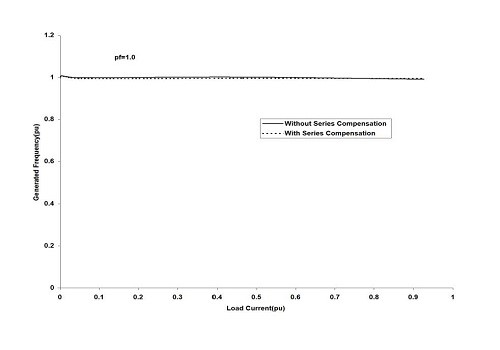
Figure 9: Variation of generated frequency for ‘load voltage and generated frequency control’ of SEIG-I at unity power factor load…
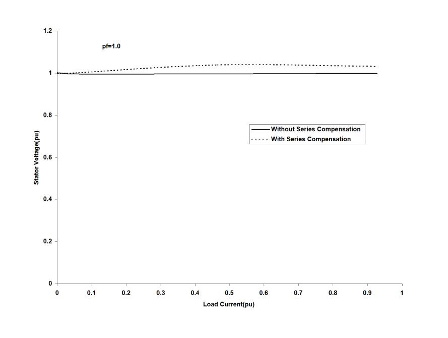
Figure 10: Variation of stator voltage for ‘load voltage and generated frequency control’ of SEIG-II at unity power factor load…
Conclusions
In this article a new model based upon genetic algorithm is proposed to control the terminal voltage and frequency of a self-excited induction generator.
Simulated results as obtained using proposed model GAA are compared with the experimental results on two test machines.
Close agreement between the simulated results and experimental values confirms the validity of proposed modeling.
As evident from simulation results, proposed modeling is effective to control the generated voltage and frequency of the machine.

If you want to share any thought or feedback on this article then please leave a comment below.


