

The use of conventional sources of energy like wood, coal etc pollutes the environment and give rise to global warming. Sun is a renewable source of energy and is safe for the environment. Solar energy is one of the popular and efficient source of energy. It is obtained from the sun by collecting and converting the solar radiations into electrical energy. Solar energy is being utilized in several sectors like engineering, irrigation, medical etc and raising the overall efficiency of power generation. About 4-7kWh/m2 and 5x10¹⁵kWh/m solar energy falls in India in a day and in a year respectively. About 3.6×1024 Joules/year total radiations are received by earth and environment. A solar cell is the smallest component in solar panels that changes the radiated solar energy into electrical energy. These solar panels are installed in an open atmosphere and subjected to the environment directly. This direct contact of solar panels towards the environment develop certain defects in solar photo-voltaic panels. These defects are degradation, discoloration of solar panels, depositions effects like bird deposition, dirt and dust deposits on panel surface, shading effects, fault in solar panel components etc. Inspection of solar panels improves the health condition as well as the overall performance of solar panel and improve power generation. Thermographical techniques give best results for performance analysis of environmental conditions in terms of temperature analysis using thermal imaging camera.
Basics of Solar Cell and Panels
Solar cell is the basic element in solar photo-voltaic panel. When solar radiations fall on a solar cell, it absorbs the solar radiations and convert the absorbed solar radiations into the electrical energy. The figure 1 shows the equivalent circuit diagram of a solar cell.
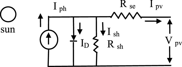
Figure 1: Equivalent circuit diagram of a solar cell
The output current IPV of a solar cell can be written as
Where, Vpv is output voltage of photo-voltaic cell, Iph is photo-voltaic generated current/ photon current/ Insolation current/ current produced by Incident light, I0 is diode reverse saturation current/ leakage current of diode, ID is diode current/ Shockley diode equation, VD is voltage drop across diode, Rse is series resistance, Rsh is shunt resistance, VT is thermal voltage and is equal to (KT/q), K is Boltzmann constant, T is cell’s operating temperature in kelvin, q is charge of an electron, η is Ideality factor of diode/ panel quality factor. The solar panels may be different types depending upon the photo-voltaic technologies used. These photo-voltaic technologies may be divided into the two types namely Crystalline silicon type and Thin film type. The Crystalline Silicon PV cells can be Mono-Crystalline and Poly-Crystalline PV Cells. Thin film PV cell consists of Cd Te (Cadmium Telluride), CIGS (Copper Indium Gallium Selenide), and a-Si (Amorphous Silicon). The fig. 2 shows a complete diagram of 72 cell Mono crystalline solar photo-voltaic module.
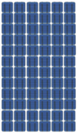
Figure 2: Monocrystalline solar photo-voltaic module
Method of Thermography
Infrared radiations were first discovered in 1800 by Frederick William Herschel, a German Astronomer. A thermal camera can detect the energy emitted as heat from any object, whose temperature is above absolute zero (-273°C). Thermography is a technique of converting infrared radiations into thermal images known as thermogram. It uses a thermal camera which captures thermal images without making a physical contact to the object. These thermal images known as thermograms, are the colourful patterns of the object representing the temperature.
Effect of Environmental Conditions on Solar Panels
Solar panels remain directly in contact with open environmental conditions, therefore, defects emerging in solar panels cause heat, affect solar power generation and reduces life of component. Some of these defects are visible by naked eye but some are not visible by naked eye. The visual effects of solar panel include corrosion of panel frame, degradation defects (cracking of the encapsulant surface, yellowing, browning of cells, delamination of cells, discolouration of cells etc), open circuit, short circuit, debridging, bubble and ruptures at back of solar panels. The effect of shadow of tree leaves, shadow of building, deposition of snow, dirt, dust, soil etc are not visible by naked eye but are one of the reason for other problems like hotspots, reduction in power generation in the solar panels. Today solar photo-voltaic systems are used in various fields like military field, medical/health care, civil, mechanical and aerospace infrastructure, electrical etc which need a continuous inspection against these defects in order to work in satisfactory and reliable manner.
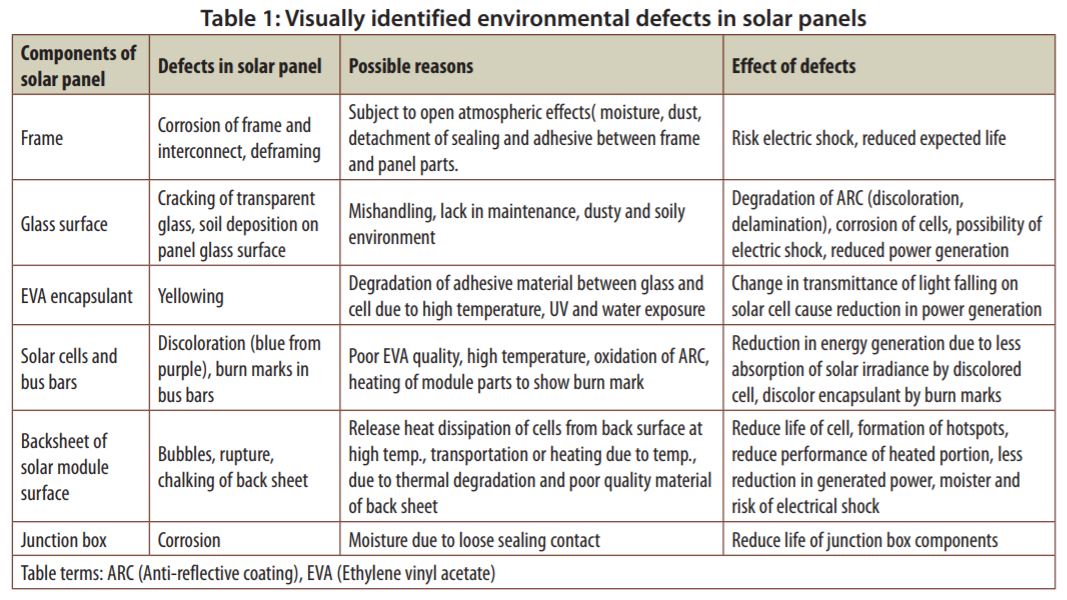
The table 1 gives the description of visually identified degradation defects found in various components in solar photo-voltaic panels. The table 1 systematically explains the common defects of various component in solar photo-voltaic panel, with possible reasons and their effects. First, it explains corrosion of frame, de-framing and defects arise during interconnecting of frame. Then problems due to glass surface are discussed like cracking of glass surface, soil deposition and its visual effects like discolouration of EVA etc. After then problems in EVA encapsulatant are discussed like yellowing with possible reasons and effect. Discoloration and burn marks of solar cells and bus bars is also being focused. Next the defects of back sheet of solar module like bubbles, ruptures are also explained. Finally, the defects occurring in the junction box of solar panel are also discussed.
Work to Study Condition of Solar Panels in Environmental Conditions
The experimental work performed to study the condition of solar panels in practical environmental conditions include two sections. First Section was to identify the environmental defects in solar panels using visual inspection i.e., the defects clearly visible by naked eye. The visual inspection involve physical identification of the environmental defects and capturing the normal camera photographs. The Second Section involves effect of shading of tree on solar panels power generation using a thermal imaging camera. Electrical measurements for power generation under no shade and under shade of tree are also done.
- Visual Identification of Environmental Defects in Solar Panels
The visually inspected defects in solar panels are shown from fig. 3(a) to fig. 3(b). Fig. 10(b).
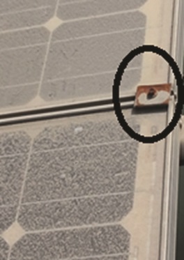
Figure 3(a): Corrosion on the interconnecting joints of solar modules
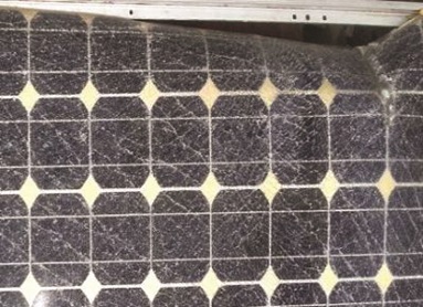
Figure 3(b): Deframing of solar module
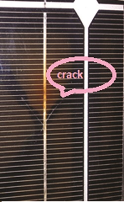
Figure 4(a): Crack on a small part of glass surface
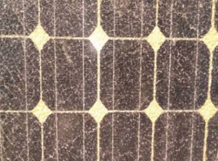
Figure 4(b): Cracking of the complete glass
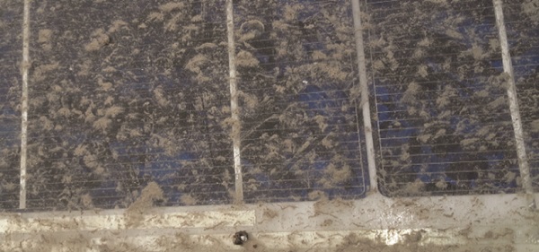
Figure 4(c): Soil deposition on the solar module surface
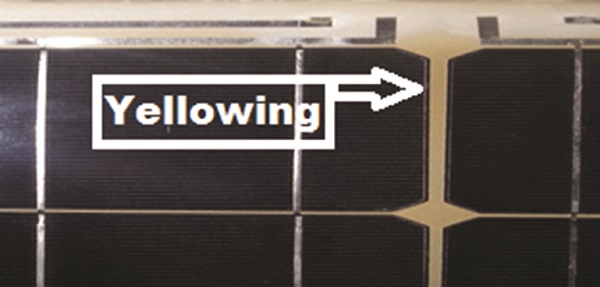
Figure 5: Yellowing of solar panel surface
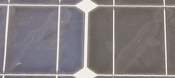
Figure 6: Discoloration of solar cell
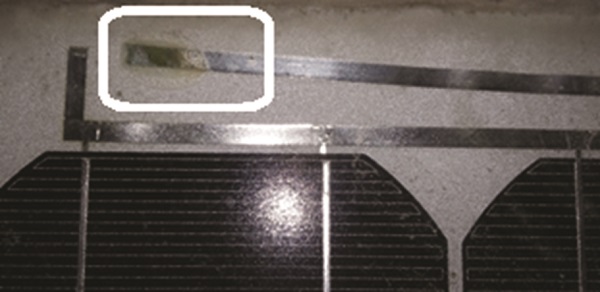
Figure 7: Burn marks on the bus bars
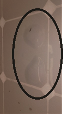
Figure 8(a): Bubbles on the back sheet of solar module surface
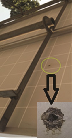
Figure 8(b): Rupture on the back of solar module surface
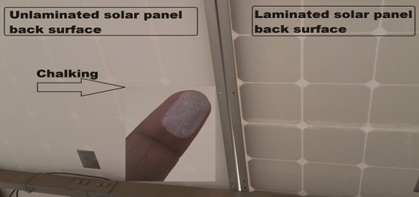
Figure 9: Chalking at back surface of unlaminated solar panel
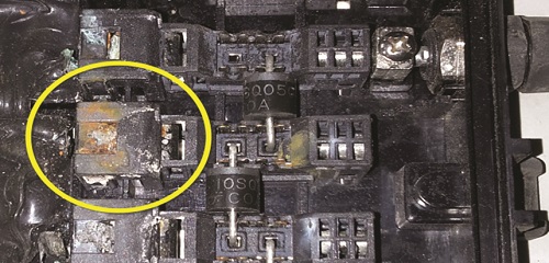
Figure 10(a): Corrosion in junction box
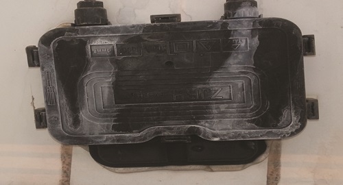
Figure 10(b): Moisture over the cover of junction box
The Fig 3(a) shows the corrosion on the joints used for connecting one solar module to another. Fig 3(b) shows deframing of solar panel frame. Deframing can occur due to ageing effect when solar panels are exposed to open atmospheric conditions.
Cracks of glass surface can affect the solar cell as well as bus bars. The glass surface defects are shown in the fig 4(a) and fig 4(b). The effect of a small crack at glass surface on solar cell can be seen in fig 4(a). The fig 4(b) shows the cracking of the complete glass surface. The soil deposition on solar panel surface can also be visualized easily. The fig 4(c) represents a heavy soil deposits on the solar module surface.
Yellowing is a common problem in solar panels. The Fig 5 shows yellowing of the panels due to the degradation of EVA (ethylene vinyl acetate).
The discoloration of solar cell is also one of the mostly occurred problem in solar panels. It is basically due to high temperature and oxidation of ARC (anti-reflective coating). The color of the solar cell changes from purple to blue. The change in color of solar cell allows to fall less amount of solar irradiance on solar cell, as a result less amount of energy is generated. Fig 6 shows the discoloration of the solar cell. The color of the left solar cell became less blue than the right solar cell which is dark blue.
When the temperature of a particular part becomes very high, then the hot area produce burn masks. Such burn masks on the bus bars can be seen in fig 7. It can affect the life of encapsulant if neglected or even not treated with a proper care.
There may be visual defects at the back sheet of solar modules. As the module back sheet allows to dissipate the heat of the solar cells, there may be a possibility of the emergence of bubbles. It occurs when some gases are released during the chemical reaction of encapsulant and creating an air chamber. The temperature of cell above the bubble becomes high because of less dissipation of heat. Rupture is an another defect exists in back sheet of solar module surface. It can be due to high temperature, mishandling of modules during transportation. Both bubbles as well as rupture affect the generation of power by a small amount. Fig 8(a) shows two bubbles on the back sheet of solar module surface and fig 8(b) shows a rupture on the back of solar module surface.
Generally, the back sheet of solar panels are laminated to get good finish, durability and safety against any other degradation defects. When the quality of back sheet material is poor or the back surface is rough, deposition of chalking is observed. Chalking is a white powder at the back sheet of solar panels commonly occurs due to thermal degradation or poor quality materials used at the back sheet of solar panels. It fails back sheet insulation and cause electrical shock also. The fig 9 shows two solar panels with unlaminated and laminated back surface along with chalking observed from unlaminated back surface. There may be corrosion in the junction box, situated at the back surface of solar module. The main reason of the corrosion of the junction box is the moisture. If the closing cover of the junction box is not fixed tightly then there are chances of corrosion. Fig 10(a) and fig 10(b) shows the photograph of the corrosion present in the junction box components and moisture on the outer cover of junction box. The corrosion may lead to reduce the life of the junction box components.
Effect of Shading on Solar Panels using Thermal Imaging Camera
Shading of tree, bird deposits, cement deposits, soiling are some of the environmental factors which cause reduction in power generation from solar panels in heat form. The heating of solar panels due to shade is not be visualized by naked human eye and can damage the affected area. Therefore, thermographical techniques are like thermography is used.
Effect of shading of tree: When shade of tree falls on solar panels, the solar cells under shade attain less solar irradiance as compared to unshaded solar cells therefore unshaded solar cells act as a load and draw power instead of supplying. This causes formation of hotspots on shaded areas of solar panel surface and release heat. The temperature of hotspot area becomes more which may damage the solar cell. The second important issue is regarding loss of power which is wasted during shading of solar cell. A lot of generated power is radiated in heat form when hotspots are formed during shading effect.
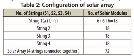
The measurements were performed on 25.04.17 at the roof of a library building in faculty of engineering of Dayalbagh Educational Institute Campus over which solar array was installed with facing towards south. The library building is surrounded by trees in plenty on eastern side and few on western side, there was a building on north side. The table 2 shows detailed configuration of complete solar array consisting of four strings of solar panels.
The shade of tree falls on solar panels after 2.00 pm, so two cases were formed:
Case 1: Thermal method with no shade of tree on solar panels
Case 2: Thermal method with shade of tree on solar panels
For case 1, the measurements were performed at 10.30 am when there was no shade on solar panel surface. Normal camera photographs and thermal images were captured along with other thermal and electrical parameters. For case 2, measurements were performed after 2.30 pm when shade of tree covers almost half portions of solar panel string 1, string 2 and string 3. String 4 is free from shade. Therefore, solar irradiance of string 1 and string 2 is low as compared to string 3 and string 4. Normal camera photographs and thermal images were captured with electrical parameters. The fig. 11(a) to fig. 11(h) and fig. 12(a) to fig. 12(h) show normal camera photographs and thermal images of solar panels for two cases considered above. The thermal images show areas of heating with maximum temperature, minimum temperatures on scale.
Fig. 11(a) to fig. 11(h) shows normally captured photographs for string1, 2, 3, 4 respectively under no shade of tree, fig 12(a) to 12(h) show normally captured photographs for string1, 2, 3, 4 respectively under shade of tree.
The fig 11(a), fig 11(b), fig 11(c), fig 11(d) are the normal photographs of string 1, string 2, string 3, string 4 respectively under no shade of tree i.e., for case 1. The fig 12(e), fig 12(f), fig 12(g), fig 12(h) are the corresponding thermal images showing high temperature represented by bright color. The fig 12(a), fig 12(b), fig 12(c), fig 12(d) are the normal photographs of string 1, string 2, string 3, string 4 respectively under shade of tree i.e., for case 2. The fig 12(e), fig 12(f), fig 12(g), fig 12(h) are the corresponding thermal images showing low temperature represented by dark color with hotspots clearly visible.
Electrical measurements for shading effect of tree
To study the effects of shade of tree on solar panels more precisely the corresponding electrical parameters were measured along with thermal measurements, which include output current, output voltage and output power of complete solar array. Table 3 shows electrical parameters for case 1 and case 2.
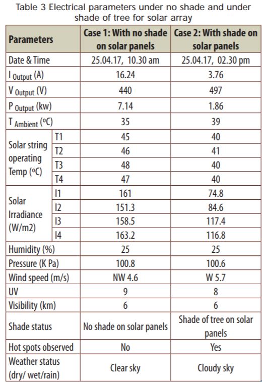
Table 3 shows that the output current as well as output power of solar photo-voltaic array reduces as solar panels come under the shade of tree. It also shows individual temperature, solar irradiance of solar strings with atmospheric parameters. Hotspts were noticed for solar cells which are shaded by tree showing loss of generated solar power in heat form
The fig 13 and fig 14 show the bar chart for operating temperatures, solar irradiance for four string with no shade of tree and with shade of tree respectively.
The fig 15 shows bar chart of the output current and output power of solar array with no shade of tree and with shade of tree respectively showing reduction in output current and output power of solar array due to shading effect of tree.
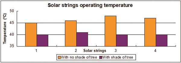
Figure 13: Operating temperatures of four solar strings with no shade of tree and with shade of tree
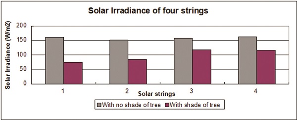
Figure 14: Solar irradiance of four solar strings with no shade of tree and with shade of tree
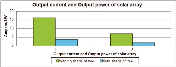
Figure 15: Output current and output power of solar array with no shade of tree and with shade of tree
Conclusion
This paper shows a study of environmental defects generally occur in solar panels with their visualization methods. Some open environmental defects are visible by naked eye can be identified by visual inspection. The effect of shading is one of the important factor considered in the condition monitoring of solar panels. The shading of tree on solar panels increase the temperature of solar panel surface, which is not visible in the photographs captured by normal camera. Such heat effects can be detected by thermal imaging camera easily. The shading of tree on solar panels affect the power generation of solar panels, therefore, thermal analysis of solar panels with no shading and with shading is also included by formulating two cases. So a comparison is obtained between case 1 and case 2 with the help of normally captured photographs and thermal images to show how shadow of tree affects the generating power of solar panels. The bar charts shown in fig 13 and fig 14 represent variation of operating temperature, variation of solar irradiance for solar panel strings 1, string 2, string 3 and string 4 respectively. The shading of tree give rise to hotspots and causes heat and reduction of generated power as shown in fig. 15.

If you want to share thoughts or feedback then please leave a comment below.


