

In the current context, for both utilities and the self-governing power plant investors, the major challenge is being the integration of the wind power plants and other renewable based energy conversion systems on to weak distribution grids that are in operation. The standards and methodologies have been prepared to apply for the many parties and stakeholders that were continuously involved with the wind industry in the Power Sector. The key participants are the Wind Turbine (WT) manufacturers determined to abide by well drafted features and characteristics, the WT buyer in specifying the power equipment characteristics, the Wind turbine operators, and finally the planner or regulator who may be essential to verify and monitor that the drafted power quality characteristics are met as per standards. They also judge to determine the significant impact of the wind turbines on the power system network quality of service.
In fact, it is always essential and recommend for the schemer or regulator of the electrical power system network, who needs to determine, control and regulate the grid connection required for the wind turbine in the extent of power quality. The present international standards like IEC 61400-21 & IEC 61400-1are the major contributors to evaluate and improve the power quality of grid connected based wind turbines, particularly for the evaluation of bang that different technologies may face in weak sensitive systems.
The essentiality to regulate or control the grid connection of wind turbines and its impact on the local consumers was postulated by the International Electro- technical Commission (IEC) – that published a new standard i.e. IEC 61400-21 associated with the measurement and assessment of power quality performance and characteristics of grid connected wind turbines. In this the main factors and limitations that characterize the quality of wind power are identified and certain test methodologies applicable to Wind Energy Conversion Systems (WECSs) are established in standard and the maximum flicker emission levels per wind turbine are well definite with limits. Moreover, a number of Transmission System Operators (TSOs) are also specifying the applicable grid codes for the wind power turbines confined with wind plants.
Power quality features
Even though the necessities of the wind power turbines were challenging the manufacturers, they should comply and respond as requested by the TSOs. The major issues being the grid codes were issued to comply with national and regional grid characteristics due to their intrinsic nature but are typically non-general and local-dependent which prevent from a normalized standard approach.
The characteristics of the wind turbine in provisions of the quality of power are defined in IEC 61400-21. In addition, they can also come up with power ramp control requirements along with Ride Through Fault (RTF) capability. Network support can be used to improve the PCC short-circuit power in order to accept for the interconnection with huge wind power plants in a given power network area. They provide the recommendations to carry out measurements to assess the power quality distinctiveness and performance of grid connected wind turbines.
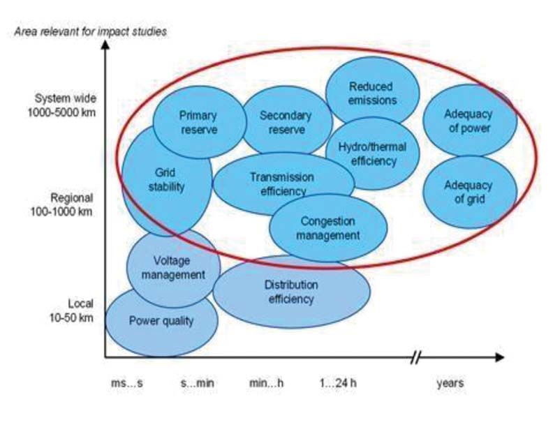
The main system impacts concerns to wind power are highlighted in Fig 1. Though, IEC 61400-21 mainly prescribes the measurement techniques for characterizing single wind turbines, there are methodologies and models developed which enable for certain pre-defined conditions, to extrapolate the single turbine unit parameters to the typical quality characteristics of wind farms.
Finally, we can say that the assessment of the WT’s power quality is nothing but the assessment of the turbines voltage quality implies the steadiness of grid itself because, the wind power turbines are primarily associated with the local distribution grid. The main concern was about WTs probable impact on the quality of voltage and not on power system network operation.
This difficulty has been determined with the emergence and development of enormous wind farms that become significant portion of the power system network. Wind turbines may be successful to the main frequency control, but with the price of dissipated energy. In Table 1, the influence factors with their particular distinctiveness to control the quality of power for the wind turbines is listed out.

Moreover, the latest technology allows for large global wind power penetrations and also attractive for island systems. The control of both active power and reactive powers is possible in transient as well in steady state conditions, fortunately with the present-day technology available. But still, wind plant designers and developers facing the problem from the local utilities in integrating the power generated by independent power plants with the existing grid. Wind, being a source of spatially dispersed renewable energy, still induces a negative effect on the system planners and also operators. The concern of the factors with high impact on the quality and control of the wind-based power stations turn out to be prime aspect to pay attention. In Table 2, the developed parameters are adapted to the wind-based power as embedded generation, to proceed like quality indicators as listed out.

For few areas in which wind may have a high relation or correlation with the seasonal effects like seasonal tourism in windy hill areas, the regional integration of the wind power sources possibly together with some energy storage may avoid the fortification of the transmission line grid and likely benefits the power system network as in total.
Technology of the wind turbine
The distinctive wind behaviour in a wind farm based on squirrel cage induction generators, delivers inconsistent power to grid network. The noted active power along with the reactive power flow in either case depends on national or regional rules and regulations so called “wind power trade-marks” can contribute to flicker emissions and to affect the average voltage profile. In fact, this can be countered on by installation of reactive compensation mostly as a central cabinet of the wind farm. The employ of doubly-fed induction generators (DFIGs) or generators with complete rated frequency converters commonly offers lower fluctuations in particular active power output as a whole, and also improves the reactive compensation capabilities as well.
Grid conditions at PCC
Lessening of voltage quality because of the inter connections of the wind-based generators may execute limits to the link of large wind plants in a given part of the electrical power system network. Basically, the most related factors linked with the grid characteristics, posing influence on voltage quality is the equivalent line impedance. This method used to evaluate about the possibility of such connection mainly involves three steps, in accords with Electromagnetic Compatibility (EMC) relevant standards. The commonly introduced parameters in the grid integration studies are the short circuit power at interconnection and phase angle of the grid interconnection transformer or substation Sk and jk. They are also referred in the specific IEC, as standard parameters at the Point of Common Coupling (PCC). Moreover, this is not always feasible because of economic reasons – and hence voltage quality problems may enforce actual limits to the connection of the large wind power plants, but also based on the wind turbine technology that is existing.
- Documentation of the acceptable planning levels in receiving network, in context of voltage, especially power quality harmonics and flicker coefficients.
- Provision of the distortion limits to the generation capability and facilities, considering with the influence of adjacent power networks.
- Assessment of the acceptable limits for the harmonic current injections and flicker for each wind park alone.
Wind farm design and control
This wind farm topology is basically habituated by the wind turbine micro siting in order to evade some turbines to work under the wake of others. It is most commonly accepted that the power variations whose equivalent representation in the IEC power quality standard is the flicker and produced by some wind turbines tend to cancel by a factor of 1/ N, being ‘N’ the number of the turbines in a park of electric cluster. Though the wind park topology is not spoken in any present standard, it influences on a wind power farm dynamic behaviour. Hence, on this power plant’s quality is not insignificant and shall be taken into explanation.
Wind turbine power quality parameters
As mentioned before, the publication of IEC 61400-21 standard allows describing systematic parameters to illustrate the quality of power mainly voltage at that time of grid connected wind turbines. The main parameters recognized and presently used today are presented below:
Wind turbine productive structures
- Nominal power and Reference Power
- Reactive power and active power
Wind power variations
- In Steady-state: Flicker emission Long and Short-Term emission
- In Transient State: Wind turbine cut-in and cut- out Voltage ‘Dips and drops’
Imbalances and harmonics limits
- Current Harmonics versus Inter-harmonics
Methodology
The procedure presented in IEC 61400-21 aims at assessing the quality of the energy distributed to the electrical grid by wind parks or farms. This standard presents a methodology based on current and voltage measurements, engaged at the terminals of a wind power generator, principal to the simulation of voltage variations in a fictitious grid which does not have any other voltage variation sources, than the tested wind generator.
In the arrangement, the mentioned methodology is presented, from the fictitious grid model implementation, to the attainment of the applicable parameters, in continuous operation flicker coefficients, C(Yk,Va), as well as in switching operations voltage change factor, ku(Yk) and flicker step factor kf (Yk).
Fictitious grid notation
The fictitious grid is signified by an ideal voltage source, with instantaneous value u0(t), and by an impedance formed due to the series of a resistance, Rfic, with an inductance, Lfic as indicted in Fig. 2. The wind generator is characterized by a current source, im(t), whose instantaneous value equals with the measured current value, of the studied phase. In this method, the voltage level at the wind generator terminals, ufic(t), can be assessed, considering into account the ideal voltage source, u0(t) and the electrical angle of the fundamental of the measured voltage, am (t).

By complex representation, one can accomplish that:
![]()
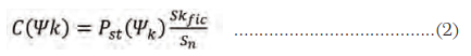
Where Un is the RMS value of the nominal voltage of the grid and Skfic, and Yk represent, respectively the short circuit power and angle of the fictitious grid.
Continuous mode of operation
In continuous operation, the parameter that licenses assessing the quality of the energy transported to the grid under consideration by a wind generator, in terms of the voltage variations, is the flicker coefficient, c(Yk,va). For each grid impedance phase angle (Yk = 300, 500, 700, 850) and for each wind speed delivery (wind means speed va= 6, 7.5, 8.5, and 10 m/s), the following process should be repeated:
The measured values series (3-phase instantaneous current and voltage at the main terminals of the wind power generator and wind speed) agree to get the time series of ufic(t). These measures are processed to determine the flicker coefficient as being a function of the grid impedance associated angle and the respective wind speed distribution.
The Ufic(t) time series form the flicker algorithm (flicker meter) input, whose development was based in the IEC 61000-4-15, and already presented. The output value of the mentioned algorithm is a flicker emission, Pstfic.
The flicker coefficient, by taking into account only the requirement to the fictitious grid impedance angle, is given by equation (2), where ‘Sn’ is the apparent power of the wind turbine.
The frequency of incidence of wind speeds, f y, i, is described by a Rayleigh distribution; the relative frequency of occurrence, fmi, is then calculated, for each wind bin. This enables the calculation of the weighted factor, for each wind speed bin (each bin comprehends 1 m/s), between the cut-in speed, Vcut- in , and 15 m/s, through wi= f y,i / f m,i.
The weighted accumulated distribution of the measured flicker coefficient is specified by equation. (3), where Nm, i, c <x, represents the number of flicker coefficients lesser or equal than ‘x’, for class i, and Nbin is the total number of classes.

The flicker coefficient is the 99th percentile of the weighted accumulated distribution.
Switching mode of operation
For switching operations the limits that allow approximating the quality of the energy brought by wind generators, in terms of the voltage dips, are the voltage change factor, k u(Yk) and the flicker step factor, k f(Yk). Therefore, the following procedure has been applied.
Equal to the event of continuous operation, with the single difference that the 3-phase instantaneous measured current and voltage, at the end terminals of the wind generator, should range adequately long time period, Tp, like for instance 60s, in order to guarantee the disappearing of the switching operation transient state.
Equal to the case of continuous operation.
The flicker step factor, which represents a normalized measurement of the flicker emission due to a single wind power turbine switching operation, is obtained by applying the equation (4).
![]()
The voltage change factor, which represents a normalized measurement of the voltage variations due to a wind turbine switching operation, is obtained by applying equation (5), where U fic,min and U fic,max are, respectively, the minimum and maximum RMS values taken by the fictitious grid voltage, during the switching operation.
![]()
Both factors are computed, as last result, as the average value of all the obtained 3-phase values.
Response of wind to voltage drops
The existing practices and experiential models to infer the power quality of wind-based farms from the power quality parameters defined and developed for single grid connected wind-based turbines are discussed with the option for enunciation between wind turbine power quality standards and the national or regional grid codes.
The concern is all about the Low Voltage (LV) ride through faults LVRTF or RTF capability during the faults. The response of the wind turbine to the voltage drops detailed in Table 3 shall be stated for each wind turbine that operating at a) between 0,1 Pn and 0,3 Pn and b) above 0,9 Pn.
The specified response will comprise results from two consecutive tests of each case (VD1-VD6) by the time series of active power, reactive power, active current, reactive current and voltage at the wind turbine end terminals for the short time prior to the voltage drop and until the effect of the specified voltage drop as decreased, but also the wind turbine operational mode shall be stated.
Adjustment of active and reactive power set-points
The aptitude of a wind turbine to contribute in an involuntary frequency control scheme is carefully linked to its ability to operate in active power linked set point control mode. Optional tests and measurements for example pitch angle and rotational speed may be generally carried out and stated for more detailed valuation of simulation models and conformity with specified grid code practices and requirements. The test is essentially for confirming wind turbine response to voltage drops due to grid faults that occur. The basis for this is validation of numerical simulation models wind turbine. The tolerances towards the voltage drop are represented in figure 3.

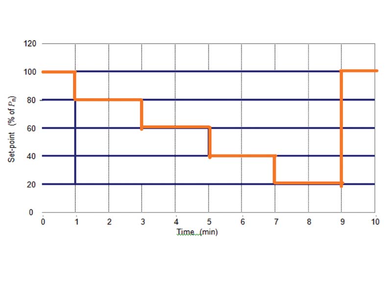
The presentation of the wind-based turbine to operate in active power Set-Point Control Mode (SPCM) will be branded by test results presented in a graph. The graph shall show accessible and calculated active power output during operation at set point values being adjusted from 100% down to 20% of rated power in steps of 20% with 2 min operation at each set-point value that is shown in Figure 4.

The capability of the wind-based turbine about the highest inductive reactive power and the highest capacitive reactive power of the wind turbine is stated in Table 3 as 1 min average values as a function of the 1 min average output power for 0 to 100% in steps of 10 each for the specified rated power.

The reactive power set-point control shall be labeled by a table and a graph as the measured reactive power at reactive set point value is equal to zero for the operation at 0 to100% in steps of 10 each active power output.
The graph(s) shows the measured reactive power during a step change of the reactive power set-point as indicted in Figure 5. The active power output, measured as one minute average values, will be approximately 50% of specified rated power. The reactive power shall be 0.2s average data.
Conclusions
Finally, to authenticate the wind farms power quality, definite algorithms and number of simulations are required to be done to get match with the real time. The end results shall be compared with obtainable experimental results from certified institutions, about the defined wind park (farm) power quality indices.
The local grid conditions in a case-by-case approach, makes possible to avoid ultimate negative impacts in the utility grid rather than by using restrictive thumb rules.
Different power quality analyzers must be used to record the various events, such as sag, swell, transient, flickering, and harmonics, in order to assess the power quality parameters of a grid-connected wind farm with variable speed generators.
With DIgSILENT software, a dynamical model of the wind turbine with a control strategy may be created.
According to IEEE and IEC standards, the following parameters need to be examined and assessed: voltage, current, frequency, active, reactive, and apparent power, power factor, and harmonics. The development and use of numerical power quality tools are under progress, which enables the utilization of dynamic wind park models to assess the wind farms power quality. The possibilities of extrapolation from standards to grids and the issues of generalized grid codes are discussed.

Arjuna Rao M. Tech (Power Systems) NIT, Tiruchy, M.B.A from Bangalore University and PGDEEMEA from Annamalai University. He joined CPRI in 2007 and currently holding the post of Joint Director. His areas of interests include Power System Analysis, LV switchgear and Distribution Transformers. He is a Fellow in Institute of Engineers (FIE) and IEEE Professional Member in Power & Energy Society. He has more than twenty-five publications in in the area of Power Systems, Distribution Transformers, CT’s & Switchgear. He is presently pursuing his Ph.D.

Dr. H. R. Ramesh, is currently working as Professor & Chairman in Dept. of EEE, UVCE, Bangalore University having more than 28 years of Teaching Experience. He has been guiding several Ph.D. students in the areas of expertise Power Electronics, Multi level Inverters, Power Electronic applications to Renewable. He has several International and National Publications to his credit.


