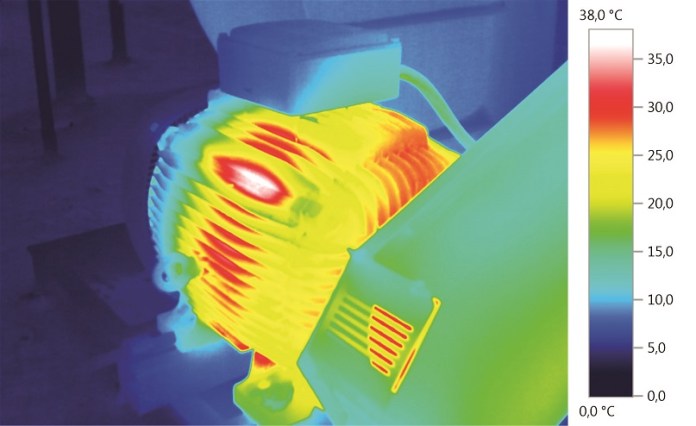
When it comes to maintaining electrical and technical systems, thermography has proved to be an indispensable aid. With the help of invisible infrared radiation, it is not only the function and condition of electrical and mechanical systems that can be monitored reliably. Weak spots and wear can also be detected at an early stage and non-destructively and thus remedy can be provided in good time. Furthermore, thermography provides excellent services for quality control and fill level measurement in production plants. In facility management, for example, it enables optimum control of heating systems as well as simple and safe testing of electrical systems.
No wonder then that the use of thermography is required in various standards and guidelines and companies are required to regularly assess the equipment and facilities thermographically. Companies that refrain from regular thermographic inspections will be subject to considerable financial and legal risks in the event of personal injury and property damage.
This article will introduce you to the most important fields of application of thermography and demonstrate how you can significantly improve your maintenance processes and system availability with the aid of thermal imagers.
Thermography for more safety and efficiency in facility management
Plant operation and safety, operating costs, and energy consumption – facility managers not only have to keep an eye on a number of factors, but also have to improve the efficiency of systems and processes at the same time.
Inspecting electrical systems
Overheated connections in a control cabinet indicate potential or actual defects. A thermal imager from Testo can detect anomalies such as these without contact and during operation, before downtimes can even occur.
Discover the energy-saving potential
A thermal imager allows concealed weak spots, thermal bridges, mould or faulty installation to be detected in a building. Especially in existing buildings, a thermal imager can be used to uncover large potential energy-savings fast and easily.
Thermography makes preventive maintenance easier
Unscheduled costly system downtimes can be prevented to a large extent by regularly checking electrical installations, control cabinets and mechanical components. Carrying out thermographic inspection a second time reduces a system’s rate of failure by around 80 percent and provides an added safeguard against fire.
Defining the scope of inspection
Before beginning the inspection tour, the thermographer or plant manager needs to define a few aspects to include:
How extensive does the inspection need to be? At what intervals are the tours to take place? And which thermal imager meets the requirements?


Defining priority criteria
Identifying the risk doesn’t mean it is automatically eliminated. When and how a problem is resolved – immediately, as fast as possible, at the next opportunity – is decided by the thermographer or plant manager. On the one hand, rectifying all identified thermal anomalies immediately would
be too inefficient and costly. On the other hand, a component’s temperature limit also depends on its function. It’s therefore advisable to classify the inspection results, for example, into three priority classes:
Class A (red)
A severe problem that requires immediate action.
Class B (orange)
A serious problem that needs to be resolved within a week.
Class C (yellow)
A problem that needs to be resolved the next time the system is scheduled to be shut down.
The applicable standard regulations, type of system, and previous experiences are primarily referred to in determining these priority levels. The aim has to be the efficient operation of a system with as little interruption as possible while ensuring the greatest level of work, equipment and environmental safety.

Challenges faced in Thermography and Advantages offered by Testo Thermal imagers
- Delta T calculation
The Delta T function allows temperature values from two measuring points of choice to be directly compared with each other and the differential temperature to be read (testo 868, 871 and 872).
- IFOV warner
The IFOV warner automatically shows the measurement spot size on the thermal image at any distance to the measuring object. This prevents measurement errors occurring. The measuring object must be within the IFOV rectangle (with testo 868, 871 and 872).
- ScaleAssist
The testo ScaleAssist optimally adjusts the thermal image scale automatically.
This allows the creation of objectively comparable and error-free thermal images of the heat-insulating characteristics of buildings (with testo 868, 871 and 872).
- App
The testo Thermography App enables use of a smartphone or tablet as a second display and remote control. This means reports can be easily and quickly created, saved and sent online (testo 868, 871 and 872).
- Connectivity
In conjunction with the testo 770-3 clamp meter and testo 605i thermohygrometer, even more informative thermal images can be created. Their measurement results are easy to send to the thermal imager via Bluetooth so that moist surfaces or the load in the control cabinet can be detected fast (with testo 871 and 872).
- Fully radiometric video
The measurement data can be exported in different formats for live images and measurements in real time. By setting up to 15 measuring points, a differential temperature diagram can be presented (with testo 885 and 890).
- Focal distance
Thanks to a minimal focal distance of 10 cm, temperature distribution and development can be detected easily and accurately even on small electronic components (with testo 875, 885 and 890).
Source: testo.com


