Underground coalmines require number of electrical equipment for production of coal and for safety of the miners working belowground. The use of electrical equipment in gassy mines is governed by Coal Mines Regulations (CMR) 1957 and Central Electricity Authority (CEA) 2010 (earlier Indian Electricity Rules 1956), which allow use of electrical equipment having type of protection flameproof (Ex ‘d’), increased safety (Ex ‘e’) and intrinsically safe (Ex ‘i’) under 181(3) provision of CMR. There are other protection techniques used for design of electrical equipment for use in hazardous areas of surface industries, which basically ensures the prevention of explosion or fire due to electricity in such areas.
Categories of underground coal mines as per CMR as per gassiness:
The underground coal seams in working mines in India are categorized into Degree I, Degree II and Degree III of gassiness depending on the volume of inflammable gas present per cubic meter of coal and defined in the coal mines regulation 1957.
- The degree of gassiness of seams is defined as follows:
- Gassy seam of Degree I: A coal seam or part thereof lying within the precincts of a mine not being an opencast working whether or not inflammable gas is actual detected in the general body of the air at any place in its working belowground, or when the percentage of the inflammable gas, if and when detected, in such general body of air does not exceed 0.1 and the rates of emission of such gas does not exceed one cubic meter per tonne of coal produced (i.e. 1 m3/tonne).
- Gassy seam of Degree II: A coal seam or part thereof lying within the precincts of a mine not being an opencast working in which the percentage of inflammable gas in the general body of air at any place in the working of the seam is more than 0.1 or the rate of emission of inflammable gas per tone of the coal produced exceeds one cubic meter but does not exceed ten cubic meters (i.e. 1 – 10 m3/tonne).
- Gassy seam of Degree III: A coal seam or part thereof lying within the precincts of a mine not being an open cast workings in which the rate of emission of inflammable gas per tonne of coal produced exceeds ten cubic meters (i.e. > 10 m3/tonne).
Classification of hazardous areas of surface industries as per IS 5572: 2009 (IEC 60079-10-1 (2008)):
- Zone 0 is the area in which hazardous atmosphere is normally present continuously.
- Zone-1 is the area in which hazardous atmosphere is likely to occur under normal operating condition, and
- Zone 2 is the area in which hazardous atmosphere is likely to occur only under abnormal operating conditions.
Basic concept of electrical equipment design and selection of equipment in hazardous areas:
The ignition of flammable gases, vapors, liquids or dust in presence of oxygen contained, in the surrounding air may lead to explosion, a rapid physical or chemical reaction accompanied by an increase in temperature and pressure. Basic requirements for an explosion to take place in atmosphere are: flammable substance (fuel, gases, vapors), oxygen (air) and source of ignition. The mixture of gas or vapor with air in a proper ratio (within explosive range) is potentially ignitable mixture. Electrical parts or components can generate different sources of ignition e.g. spark or arc, hot surface and static electricity.
Special design techniques (types of protection) for electrical/ electronic equipment:
It is clear that there are two major factors which are responsible for a gas explosion, explosive atmosphere and source of ignition.
The first strategy for prevention of explosion is to take all precautions so that an explosive environment is not created. But it is not possible in the industries where gases are emitted during the process of production or extraction of coal in gassy mines. Therefore, it is necessary to protect the source of ignition in the potentially explosive atmosphere. It can be achieved by various methods. These methods or special measures used for electrical equipment during their design and use to prevent explosion which basically depends upon prevention of formation of fire triangle or on its confinement. The special measures applied to them known as types of protection.
There are eight types of protections applied to the electrical equipment for their safe use in explosive atmosphere. These special electrical equipment are known as Ex equipment. Ex stands for explosion proof or explosion protected. Table-1 shows the different Ex equipment with examples and use in surface industries.
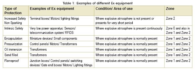
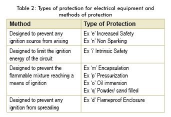
The protection may be achieved either by suitably constructing the enclosure or suitably designing the apparatus or the circuits depending on the application. In background of each protection the main thing is to prevent the contact among explosive mixture, ignition source and the supportive environment, generally oxygen (Please refer Table 2).
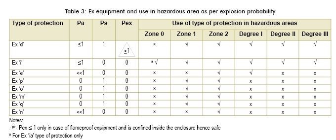
Explosion probability and selection of equipment
The probability of explosion (Pex) can be defind based on the probability of occurrence of explosive atmosphere (Pa) and probability of formation of ignition source (Ps),
Pex = Pa × Ps
It is clear that area having less probability of occurrence of explosive atmosphere (Pa) will have minimum chances of explosion. The simultaneous occurrence of explosive atmosphere and ignition source is also important. From Table-3 it is clear that the protection techniques Ex ‘n’ and Ex ‘e’ are basically designed to prevent any ignition source from arising, similarly flameproof protection is designed to prevent any ignition from spreading. In case of pressurized protection the equipment is designed to prevent the flammable mixture reaching a means of ignition.
Types of protection permitted in gassy mines as per CMR
Under Regulation 181(3) of Coal Mines Regulations-1957, flameproof, increased safety and intrinsically safe electrical apparatus and cables can be used in underground coal mines only when they are approved by the Chief Inspector of Mines also designated as Directorate General of Mines Safety.
CMR 1957 outlines use of flameproof, increased safety and intrinsically safe equipment in below ground gassy mines. These protection techniques are described here to understand the concept and method of design requirements:
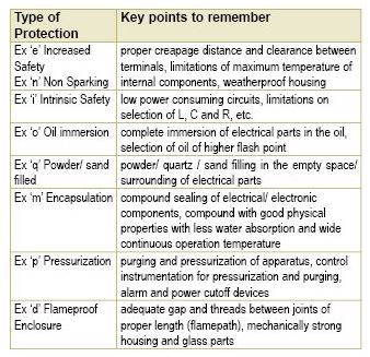
(i) Explosion Proof or Flameproof (Ex d) as per IS/IEC 60079-1
In chapter 1 of CMR 1957, the flame proof apparatus is defined as follows:
“Flame proof apparatus” means an apparatus that can withstand without injury any explosion of the inflammable gas that may occur within it and can prevent the transmission of flame such as will ignite the inflammable gas which may be present in the surrounding atmosphere.”
Performance requirements
· These enclosures allow explosion to take place inside the enclosure but do not allow explosion to permeable to surrounding hazardous area.
· They are capable of withstanding the internal explosion & their mechanical integrity remains unaffected.
· The surface temperature of enclosures does not exceed the auto ignition temperature of surrounding flammable gases while in operation.
Construction features
- Flame path and gap (length & clearance) is ensured as per volume of enclosure and gas group of the hazardous atmosphere
- Material of construction is chosen to avoid frictional sparks
Applications
In general equipments such as Control & Power panels’ etc. having arcing devices such as fuses and switchgears etc. can be designed and use as flameproof.
Chapter-XV of CMR 1957 outlines the use of flameproof equipment as follows:
“In every gassy seam of the second or third degree only flame proof electrical apparatus and equipment shall be used belowground unless otherwise provided for under the Indian Electricity Rules, 1956]….”
Use of flameproof equipment in gassy mines as per CMR:
In degree I: at any place lies in-bye of last ventilation connection
In degree II: at any place which lies in-bye of last ventilation connection and return airways and any place within 90 meters of any working face or goaf.
In degree III: at any place which lies in-bye of last ventilation connection and return airways and any place within 270 meters of any working face or goaf.
It is clear that as the rate of emission of flammable gas per tonne of coal is increasing the effective area (in terms of distance) of explosive atmosphere inside the mine from the working face and goaf is increasing.
(ii) Intrinsically Safe (Ex i) as per IS/IEC 60079-11
IS/IEC 60079-11 (2006) defines an intrinsically safe circuit as follows:
“Circuit in which any spark or any thermal effect produced in the conditions specified in this standard, which include normal operation and specified fault conditions is not capable of causing ignition of a given explosive gas atmosphere.”.
Intrinsically safe apparatus: electrical apparatus in which all the circuits are intrinsically safe circuits.
Construction features
The energy stored and dissipated during a normal or fault conditions is insufficient to ignite the surrounding flammable gases.
The surface temperature of the components like ICs, Capacitors, Inductors, resistors, etc. mounted inside does not exceed auto ignition temperature of surrounding flammable gases.
All the components / PCB track / wire cross section are chosen with high safety margins to prevent temperature rise under fault condition thus preventing ignition.
Adequate clearance and creepage distance are maintained between conducting wires
In addition with many devices safety barriers are used to isolate field devices under fault condition.
Application
In general various low power devices such as gas detectors, signaling, telephonic and communication equipment can be designed and use as intrinsically safe.
Chapter-IX of CMR 1957 outlines the use of intrinsically safe apparatus as follows:
“In every gassy seam of the second or third degree], all signaling or telephonic communication circuit shall be constructed, installed, protected, operated and maintained in such a manner as be intrinsically safe.”
Use of intrinsically safe apparatus in gassy mines
In all gassy mines: at any place all signaling or telephonic communication circuit shall be intrinsically safe.
(iii) Increased Safety (Ex e) as per IS/IEC 60079-7
Performance requirements
- Explosion inside enclosure is prevented by ensuring that ignition of flammable gases do not take place by eliminating all contributory factors like arc, spark and hot surfaces.
- The surface temperature of enclosures or components mounted inside does not exceed auto ignition temperature of surrounding flammable gases.
- These enclosures are not required to withstand explosion inside the enclosure.
- These enclosures should have minimum ingress protection of IP 54
- The power to the motors is withdrawn before attaining limiting temperature by the stator winding of the motor in case of stalled rotor condition.
Construction features
- No arcing or sparking devices such as fuse & switchgears are used. No making and breaking of contacts is allowed.
- Ignition is prevented by use of non-sparking components with higher thermal rating having safety margins to prevent sparks & rise in temperature.
- High impact resistant materials like FRP or GRP not holding static charge or metals are used.
- Clearance and creepage distances are maintained to prevent sparking between conductive terminals.
- Anti-loosening & vibration proof terminals are used.
- Enclosure is protected against possible ingress of dust and water to prevent conductive layer formation between current carrying parts.
- The source of ignition does not form when the equipment is constructed as per laid design features. The increased safety motors are also designed and assessed against any possible risk of stator winding discharge and air gap sparking in cage rotor construction of motors.
Applications
- Terminal housing, luminaries and motors.
Use of Increased safety equipment in gassy mines as per CMR:
“In degree I gassy mines,…….electrically operated or battery operated portable or transportable apparatus such as shuttle car, men or material transporting equipment of increased safety ‘e’ shall be permitted at any place with suitable monitoring devices for detection of gases, if any.”
For gassy mines of degree I, gas detector is interlocked with the Ex ‘e’ apparatus and disconnects the power to the apparatus when flammable gas is detected more than 1.25% in air.
Types of protection for use in explosive atmosphere other than coal mines
All types of protections permitted for coalmines are also applicable for surface industries. In addition, following types of protections are also used for electrical equipment for surface industries and oil mines and are described below:
(i) Non-Sparking or non-incendive (Ex n) as per IS/IEC 60079-15
Performance requirements
- Explosion inside enclosure is prevented by ensuring that ignition of flammable gases do not take place by eliminating all contributory factors like arc, spark and hot surface.
- The surface temperature of enclosures or components mounted inside does not exceed auto ignition temperature of surrounding flammable gases.
- These enclosures are not required to withstand explosion inside the enclosure.
- These enclosures should have minimum ingress protection of IP 54
Construction features
- No arcing or sparking devices such as fuse & switchgears are used. No making and breaking of contacts is allowed.
- In these types of equipment, only such components are used, which are incapable of producing sparks thus eliminating source of ignition.
- Clearance and creepage distances are maintained to prevent sparking between conductive terminals.
- Enclosure is protected against possible ingress of dust and water to prevent conductive layer formation between current carrying parts.
- The source of ignition does not form when the equipment is constructed as per laid design features. The non-sparking motors are also designed and assessed against any possible risk of stator winding discharge and air gap sparking in cage rotor construction of motors.
Application
- Motors, luminaries, terminal housing etc.
(ii) Encapsulation (Ex m) as per IS/IEC 60079-18
Performance requirements
- Ensuring exclusion of flammable substance coming in contact with source of ignition by encapsulation prevents explosion.
- The surface temperature of enclosures or components mounted inside does not exceed auto ignition temperature of surrounding flammable gases.
Construction features
- Either potting with resin or sealing compound to achieve encapsulation.
- By encapsulation ingress of surrounding ambient is prevented.
- This is prevalent for small devices & electronic components.
Applications
Static coils in ballast, solenoid valves or motors, relays and other control gear of limited power and complete PCBs with electronic circuits, zener barriers etc.
Control Components like indicating lamps, push button elements and control switches etc.
(iii) Pressurized Protection (Ex p) as per IS/IEC 60079-2
Performance requirements
- Explosion inside enclosure is prevented by purging flammable media and ensuring non-ingress of flammable media by keeping positive pressure of uncontaminated purge media.
- The surface temperature of enclosures does not exceed auto ignition temperature of surrounding flammable gases.
- These enclosures are not required to withstand explosion inside the enclosure.
Construction features
- Under this type of protection component & devices are installed inside a purge and pressurized enclosures. A positive pressure of uncontaminated air or other neutral gas is maintained inside enclosure so as to exclude surrounding flammable media thus eliminating risk of explosion.
- Flammable media is purged from the enclosure and then only internal components are energized.
- In case of failure of overpressure in purge enclosure, the alarm is initiated and in critical condition the apparatus is de-energized.
Applications
- Electrical equipment whose normal operation involves sparks, arcing or hot components and complex assemblies like large motors, transformers, switchgear and control cabinets and analysis devices.
(iv) Oil Filled (Ex o) as per IS/IEC 60079-6
Performance requirements
- Ensuring exclusion of flammable substance coming in contact with source of ignition by submerging arcing or sparking components in oil prevents explosion.
- The surface temperature of enclosures or components mounted inside does not exceed auto ignition temperature of surrounding flammable gases due to cooling by oil.
Construction features
- Oil having high dielectric strength & good thermal conductivity are very good media for spark / arc quenching.
- They are in use since very long in High Rating Power Electrical equipments like Circuit Breakers. They are also in use in transformers for cooling.
- However they have negative aspect of flammability & forming carbon particle during arc quenching.
- In spite of these negative aspect they remain a good source for arc quenching & thus used to exclude source of ignition in Hazardous area in Oil quenched equipments.
Applications
- Large transformers, switchgear, starting resistors and complete starting controllers.
(v) Powder filling / sand filing (Ex q) as per IS/IEC 60079-5
Performance requirements & construction features
- Quartz grade sand is a very good media to suppress arc / sparks and is used in sand filled equipments to prevent explosion hazard by isolating spark from surrounding hazardous gases.
Applications
- Capacitors, electronic sub-assemblies or transformers etc.
Conclusions and points to remember
The equipment protection technique gives a universal acceptance of the designed equipment for a classified hazardous location and broadly followed worldwide. To understand the concept of protection some key points can be drawn as follows w.r.t. different protections:
Acknowledgement:
The views expressed in this paper are of the authors only and not necessary the views of the organization they belong. Authors are grateful to Dr. A. Sinha, Director, CSIR-CIMFR, for all the support and necessary facilities to prepare this paper.