

Integrated Chargers
To minimize weight, volume, and cost integrating the charging function into the electric drive system has been proposed. The function can be integrated if charging and traction are not simultaneous. In an integrated charger, motor windings are used for filter inductors or an isolated transformer and the motor drive inverter serves as a bidirectional ac–dc converter. The most important advantage is that low-cost high- power (Levels 2 and 3) bidirectional fast charge can be supported with unity power factor. Control complexity and extra hardware are challenges to implementation in commercial products. A combined motor drive and battery recharge system based on an induction motor is currently used by the Ford Motor Company. A non-isolated integrated charger based on a split-winding ac motor will be used in the automotive industry. There are some applications for electric scooters and two-wheeled vehicles. A typical integrated charger system is shown in Fig. 10.
Classifications of Integrated Battery Chargers
Integrated charger topologies may be categorized based on motor count and inverter count. Each motor can be controlled by its dedicated inverter. It consists of two inverters to drive the main and auxiliary motors, and used them as an AC-DC converter for charging, while two three-phase motors were used as inductors for the converter with their neutral points connected to the grid.. The first machine plays a role in delivering regenerative energy to the battery by supplementing the driving force as a traction motor. The second machine starts up the engine or charges the battery. In the charging mode, both motors and inverters operate as an AC–DC boost converter. Disadvantages of this charger are the large number of extra components (twelve power switches, three contactors, and two motors) and control complexity. A two-motor/two-inverter integrated charger is discussed and it was shown in Fig. 11.one induction motor with a double set of stator windings comprising two motor halves.
One-Motor With One-Power Converter Topology: With one motor and one power converter, an integrated topology may be classified by motor type: Induction, permanent magnet (PM) and switched-reluctance motor (SRM) ,with isolated or non-isolated circuitry.

Non-isolated/Isolated Cases for Induction Motors:
Five non-isolated cases for induction motors have been reported. Non- isolated chargers tend to minimize size and weight. In the second, the three-phase motor and inverter together operate as an ac–dc boost converter, and the dc link voltage is stepped down to the nominal battery voltage through a bidirectional dc- dc converter. This one-motor inverter system is simpler to control than other topologies. It accesses the motor center tap to use the motor as a coupling inductor. An integral PFC charger is formed with four three-phase induction motors and their inverters. There is no extra hardware except a transfer switch. However, this integrated charger is only appropriate for vehicles with four-wheel drive. In the fourth topology, a three-level dc–dc boost converter is used as a front end for a two-wheeled vehicle. It is rearranged to act as a PWM-PFC charger in charging mode. A is a non-isolated single-phase integrated battery charger proposed and it has been installed on an electric scooter prototype and uses the propulsion inverter with an additional power rectifier and an LC filter. These are placed close to the motor. The on-board dc–dc converter consists of the three-phase motor windings and inverter switches, the induction machine is used as a line-frequency step-down isolation transformer in charge mode. A wound-rotor machine is used and the drive is modified to act as a three-phase PWM rectifier. Advantages include galvanic isolation, the possibility of bidirectional power flow, low harmonic distortion, and unity factor. Disadvantages include high magnetization currents and the extra costs of the wound rotor and contactors.


Non-isolated/Isolated Cases for Permanent Magnet Motors:
PM non-isolated topology method connects the vehicle to the grid through the machine windings. The configuration of the integrated charger is shown in Fig. 12. Each phase is connected to two parallel PWM boost converters. The grid is connected to center taps in each phase, splitting the currents into equal and opposite portions. This cancels the MMF on the stator and ensures magnetic decoupling between the rotor and the stator. No rotation is possible. However, this topology is complex as it must control three independent currents. A second concept for fast on-board charging is used. It uses the PM motor as a filter. The same converter is used both for charging and traction. The structure of this converter is similar to a typical three-phase PFC. The topology is composed of two three-phase PWM boost converters and a buck–boost dc–dc converter. A third and similar topology is applied in to a scooter with an interior permanent magnet (IPM) motor traction drive as shown in Fig. 13. For charging, the ac motor drive is operated as a three-phase PFC coupled boost rectifier. No additional filtering is needed since the PWM ripple is minimized by means of phase interleaving. Using a general model of a three-phase ac motor, the feasibility of an integral charger with other ac motors is also studied Disadvantages include the need for extra hardware, which includes a single-phase rectifier bridge with a mechanical switch to access the center tap of the motor, a capacitor, and an EMI filter. A PM-assisted synchronous reluctance has four-pole machine with a three-phase winding in traction mode. Each phase winding is divided into two equivalent parts which are shifted symmetrically around the stator periphery in charging mode.

charger for a scooter.
The traction inverter acts as a rectifier for charging. The device is equipped with two sets of three-phase windings, and the winding connections can be reconfigured from traction mode to charging mode with a relay. A contactor is used to connect the grid-side windings to the grid, as shown in Fig. 14. This charger serves as an isolated high-power bidirectional fast charger with unity power factor.

Non-isolated /Isolated Cases for Reluctance Motors:
Three reluctance machine topologies are implemented for an a compact battery- powered SRM drive for an EV with voltage boosting and on- board PFC charging capabilities, as shown in Fig. 15. Although the boost front-end dc–dc converter is external, the on-board charger is formed by the embedded components of the SRM windings and converter. During demagnetization of each leg, the stored winding energy is recovered to the battery. In charging mode, the power devices are used to form a buck–boost rectifier to charge from the utility with good power quality. SRM phase windings used as a transformer during charging in but without active PFC control. It used an extra winding on one phase of the stator to support transformer operation for a single-phase ac supply with an SRM. The rotor position will automatically align to maximum inductance over the first few cycles in charging mode. The extra winding can adjust the voltage level according to converter requirements.

CONTACTLESS INDUCTIVE CHARGING Conductive chargers use metal-to-metal contact as in most appliances and electronic devices. Inductive charging of EVs is based on magnetic contactless power transfer .

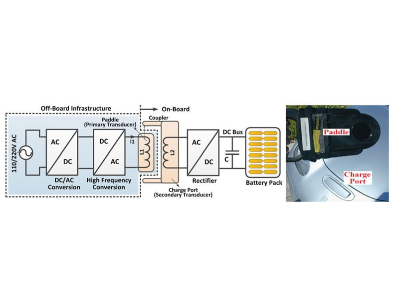
Conductive Charging
Conductive charging systems use direct contact and a cable between the EV connector and charge inlet. The cable can be fed from a standard electrical outlet (Level 1 or 2) or a charging station (Level 2 or 3). There are already several charging posts on the market. Available vehicles, including the Chevrolet Volt and Tesla Roadster, use Levels 1 and 2 chargers with basic infrastructure (convenience outlets). Conductive charging is also employed on the Nissan Leaf and Mitsubishi i-MiEV, which use either basic infrastructure or dedicated off- board chargers .The main drawback of this solution is that the driver needs to plug in the cable. This is a conventional issue.
Part 3 will be continued in the next issue of the Electrical India Magazine


