

Under the prevailing scenario, the Industries especially, continuous process industries; Commercial organizations like Data Centres and Call Centres/BPO’s etc, have to rely on a dependable Back-up power sources. For short time, back up U.P.S. with batteries are useful. For long time and heavy block loads UPS are not useful. Though, Natural Gas, Fuel cells & the renewable power sources such as Solar, Wind etc, are available for giving power back-up but due to their non-availability on 24×7 basis all-round the year, most of the Industries & Commercial organizations mostly rely on Diesel Generator sets due to easier availability of diesel at most of the places, their comparatively quick starting, there acceptability of large block loads, their effective speed/frequency /voltage regulation with load changes etc. However, where instantaneous load transfer is needed they can not replace the UPS systems as the DG sets need minimum 30 seconds to start and deliver power at the desired voltage & frequency.
Selection/Sizing of DG Sets
Environment/Site conditions impact the diesel Engine and consequently DG set performance. Various factors which impact the Selection/Sizing of the DG sets are: Altitude, Heat, Humidity, Dust and Corrosive Surrounding etc.
Altitude
As the altitude increases the air density lowers. DG set needs clean & dense air for efficient combustion of fuel. Generators to be installed at an altitude above 1000 mtr. needs to be de-rated by 1% for every 100 mtr or 328 ft. above 1000 mtr above mean sea level.
Heat
Generators are normally designed for ambient temperature of 40OC OR 104OF. When ambient temperature is more the DG set needs to be de-rated as per manufacturers specification manual.
Humidity
In a highly humid environment, there is a possibility of condensation which adversely affect the DG performance. In such a site use of space heaters for prevention of condensation is desirable.
Dust
Metallic dust like cast iron dust, sand, graphite powder, coke & lime dust, quarry and wood fibre etc, types of dust which may be drawn in to DG set by the ventilation fans may cause flash-over inside DG set Alternator.
Corrosive Surrounding
Salt and other corrosive elements may damage Alternator winding insulation. For such atmosphere additional coating of insulation during manufacture & epoxy compound as a final overcoat is essential.
For Right Sizing of the DG set there is need to know-
- The total wattage of the equipment,
- Block load requirement,
- Starting/Surge current,
- Type of load i.e Inductive/Capacitive/Resistive etc.
Apart from these factors we have to take in to consideration the projected expansion of the organization. Depending upon the projected growth, availability of space etc, a judicious decision whether to install a higher capacity of a DG set OR to install 2 smaller sizes of DG sets needs to be taken. In this connection it may be noted that at lighter load the DG set consumption is more as compared to when it is loaded up to around 80%. Secondly, if the DG set is always operated at load lower than 30% it adversely affects its overall performance especially the normal useful life. When two generators are planned & installed they can be operated independently i.e. one for critical load & other for non critical load OR one for critical load and other as a hot Standby for redundancy. Or the two DG sets can be operated in parallel load sharing mode etc. In DG set the capacity of diesel Engine should be always 10 to 20% more than max. load to which it is designed. Diversity factor of load will determine the optimum size of DG set. In case of DG set for industries the quantity & ratings of motors with their starting methods and largest size motor, influence the Right sizing of the DG set. As per C.P.C.B. norms the DG sets up to 1000 KVA rating had to supplied with enclosures complying with noise control norms.
When Right Sizing of DG Set Is Done We Get Following Advantages:
- No unexpected system failure
- No shutdown due to capacity overload
- Increased longevity of the generator
- Guaranteed performance
- Smoother and hassle-free maintenance
- Increased system life span
- Assured personal safety.
Basic Components of a Standby DG Set
A Standby Diesel Generator consist of following main parts
- Engine
- Alternator
- Diesel Tank & Fuel System
- Automatic Voltage Regulator
- Cooling& Exhaust System
- Noise Level
- Battery & Battery Charger System
- Speed Governor
- Engine Control Panel
- AMF Panel
- Synchronization panel for parallel operation of 2 or more DG sets. etc.
Engine & Alternator
There are several reputed manufacturers of Diesel Engines and Alternators. A right combination of Diesel Engine and matching Alternator based on the basic points given earlier will create a best Diesel Generator set satisfying our emergency/standby power need.As per ISO-8528 (Part-1) clause 13.3.2 the DG set engine/prime mover shall be rated at 0.85 load factor. A horizontal foot mounted, self excited, screen protected, self regulated brushless alternator having single/double bearing construction (Depending upon capacity)and having a rating of 1ph /3 ph. 230/415 V
(depending on 1/3 ph), 50Hz, 0.8 p.f. with self ventilated SPDP enclosure, F/H class insulation designed for max. ambient temp. of 40OC & having an overload capacity of 10% for one hr within 12 hr of continuous use are recommended.
Diesel Tank & Fuel system
Based on the capacity of DG set there is pre-determined fuel consumption /hour which is given in the manufacturers instruction manual. However, based on the period of power failures and business need the capacity of tank may be decided. Another deciding factor is availability of space. For deciding fuel tank capacity following points need consideration:
- Emergency Stock: How much fuel you need to store for utilization considering delay in supply of diesel.
- Lead Time for Supply: Lead time needed to procure the diesel from the outlet and the time taken for transportation of the same to the site.
- Lead Time Stock: Requirement of diesel for operation of generator during lead time.
Minimum Storage Tank Capacity = Emergency Stock+ Lead Time Stock.
Normally all DG set manufacturers provide a diesel tank of capacity up to 990 litres (day tank) depending of DG set capacity. For storage of higher quantity we have to obtain necessary approvals from Statutory Authorities. There are three types of storage tanks:
- Sub-Base Storage Tank: As the name indicates it is a tank above ground but below the DG set. It has a double walled tank constructed by using heavy gauge welded steel to prevent spillage in case of leakage. Accessories such as air vent, pressure relief wall high low fuel alarm etc. need to be provided.
- Underground Diesel Tank: Depending upon the criticality of load & Business Continuity & based on the total load requirement and number of DG set installation and the minimum storage to be kept etc, the capacity of underground tank needs to be decided. Permissions/Approvals from various statutory authorities such as local Municipality, Fire brigade, Police, Department of Explosives etc is needed. These tanks are either made of heavy gauge welded steel Or of special grade Fibre glass.
- Above Ground Diesel Tank: These are used where large number of big DG sets are used and their type and construction & Approvals/permissions needed are similar to Underground Disel tank with some additional safety precautions.
Automatic Voltage Regulator (AVR)
Main function of AVR is as under-
- To automatically control the DG output voltage accurately in response to slow changes in power Or reactive VAR demand. Normal Voltage regulation has to be plus-minus 1%.
- To limit the magnitude of voltage excursion in response to sudden changes in load
- To maintain steady state stability
- To ensure transient stability in response to system faults.
Cooling & Exhaust System
DG Sets which are of smaller capacity are normally air-cooled. DG sets are usually designed for ambient temperature of 40OC. Medium and higher ratings are usually water-cooled. Care has to be taken to ensure that atmosphere surrounding the radiator is not dusty to prevent clogging of radiator. It is mandatory to have proper cross ventilation for DG set. Enclosure temperature should not be more than 5O above ambient. Exhaust piping is normally made of M.S pipes. It is usually cladded with 50 mm thick loosely bound Resin mattress/Mineral wool/Rockwool of density not less than 120 kg/sq.mt. and Aluminum cladding of 6 mm thick. Exhaust system should create minimum back pressure. Exhaust outlet should be in the direction of wind . A silencer provided in exhaust piping and its location from engine have a direct effect on the noise level. A silencer located as close to the engine minimizes noise level. Different types of silencer such as industrial, residential, hospital grade are used depending upon the noise suppression level to be achieved. As per C.P.C.B. norms the exhaust stack height of DG set up to 1000KVA should be as follows:
H = h + .2 X Sq. root of KVA
where H = Total Exhaust Pipe stack height.
h = Building height.
For DG set of capacity more than 1000 KVA the exhaust pipe height shall be 30 mtrs or
3 mtrs above building height whichever is higher. A rain cap has to be provided at the end of pipe. Distance between rain cap and exhaust pipe should be more than diameter of exhaust pipe.
Noise Level
DG set should be provided with integral acoustic enclosure at manufacturing stage itself and maximum permissible sound level for the DG set up to 1000 KVA rating as per C.P.C.B. guidelines should not exceed 75 dB at a distance of 1 metre from the enclosure surface. In case of DG sets which are not covered by above norms the noise level has to be controlled by providing an acoustic enclosure or by treating room acoustically. They should be designed for a minimum 25 dB insertion loss. Measurement of insertion loss may have to done at different points at a 5 metre from acoustic enclosure /room and then averaged. DG set should be provided with proper exhaust muffler with insertion loss of minimum 25 dB.
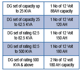
Battery & Battery Charger
Since Diesel engines need high initial starting current for cranking, the Industrial Lead Acid 12 volt batteries of high AH value are normally needed. Depending upon the capacity of the DG sets the quantity & AH values of industrial type Lead Acid batteries normally recommended by manufacturers is as under:
For battery charging a static battery charger is recommended. Depending upon the capacity of DG set suitable current rating of charger is selected. Normally 3 attempt starting setting is preferred for engine starting with a sequence of 6 seconds ON and 5 seconds Off cycle. If engine does not start even after 3 attempts it is normally locked out by Master timer and a time re-adjustment between 1 To 10 seconds is to be made before making another attempt. If engine does not start even after 4th attempt there is a need to investigate the problem otherwise the battery will drain off completely and we may have to wait till it is fully charged Or replaced depending upon the investigation.
Speed Governor
For DG sets of capacity up to 200 KVA mechanical governors of A2 class are used. As per ISO 3046/BS 5514 Electronic governors of A1 class with actuator shall be provided. Governor shall be self contained unit capable of monitoring the speed.
Engine Control Panel
DG set control panels are of Analogue OR digital type. However, now a days Digital control panels are preferred. Digital control panels are highly integrated and report real time status of all aspects i.e. fuel, engine oil, coolant levels, engine temperatures, battery status, transfer switch status, accurately and simultaneously.This helps the operator in monitoring the engine to get overview of entire system 7 to locate/identify any problem through B.M.S. in control room. Some digital control panels have a built in redundancy allowing continual system function in case of failure of a component or a part of control circuit. They have a capability to increase engine efficiency & reduce exhaust emission by providing correct rate of fuel to engine etc.
AMF & Synchronization Panel
AMF panel is normally fabricated out of 1.6mm thick sheet steel. It has to be totally enclosed, dust-damp and vermin proof, free standing, floor mounted and front operated type. It should be compartmentalized/sectionalized. All indication lamps and meters are flush mounted in front cover panel. As per ISO 2147 the panel shall have IP-42 type protection. The A.M.F. panel normally consists of relays, contactors, timers for Automatic operation on Mains failure as well as for manual operation. In addition the panel has-
- Equipment’s to test healthiness of DG set with Test mode & with load on mains.
- Energy Analyzer Or Load Manager with selector switch/button to view readings of voltage, current, KW, KWH, p.f. frequency etc.
- Audio-Visual Alarm indication /annunciation facility.
- Engine/DG shutdown device (due to fault/abnormality).
- Battery charger, excitation control, voltage regulating equipment.
- Circuit Breaker.
- Auto/manual mode selector switch and (g) Master Engine control s/w etc.
Installation of DG Set
Depending upon the KVA capacity of the DG set and load bearing capacity of the soil DG set with acoustic enclosure if it is to be installed in a separate DG set room it should have a PCC foundation (!:2:4 M-20 grade) of appro depth 150 mm above finished Gen-set room floor. It should have 250mm to 1 meter free space all around DG set enclosure. If installed in open space it may be mounted on a PCC (1:2:4 & M-20) foundation of height 2.5 times the operating weight of DG set. The DG set has to be installed on Anti-vibration pads.
Operation & Monitoring of DG set
When DG set is started and is in operation the following parameters of the DG set needed due monitoring :
- Exhaust smoke is not excessive & not too black in colour.
- Voltage and frequency is stable.
- Engine Vibration and Sound/noise is not abnormal.
- Engine temperature and pressures are normal.
- There is no leakage of lubricating oil, fuel (Diesel), coolant etc.
- There are no Fault indication/alarms.
- Operation of A.M.F. panel by manually switching off the mains power to check immediate and smooth transfer on DG set and vice-versa. All these observations are to be made on full load which should not be less than 30 to 40% of DG set capacity.
Preventive Maintenance Checks
DG sets of all the capacities need systematic preventive maintenance when following items need serious checks. Based on their conditions the remedial actions/replacements etc. need to made.
- Air locks in Cooling system for radiators, lube oil circulation etc.
- Air leakage in air intake as well as in ventilation system, wear& tear if any of hose pipes, belts etc.
- Condition of air and fuel oil filters, turbo-charges, mufflers, traps etc.
- Fuel systems for fuel levels, sediments, proper functioning of pump.
- Exhaust system for leakes, chokes & condensation.
- Functioning of various meters, batteries etc.
- Operation of bearings, brushes, speed governor, Circuit breakers etc.
- Proper functioning of all controls, relays, indication lamps.
- Auto Transfer switch functioning with proper time delays.
- Performance parameters like A.C. voltage O/P, frequency etc.
Depending upon the load criticality and redundancy requirement the Standby DG sets can be sized in a such manner that instead of installing a bigger size DG set, we may install two or more no of smaller sized DG sets depending upon availability of suitable space and which can be operated independently by suitable distribution of Critical and Non-critical loads. Alternatively, these DG sets can be operated in parallel by use of a synchronization panel for which the matching of DG set parameters are of paramount importance. This topic is being dealt with separately.

If you want to share any thoughts or feedback on this article then please leave a comment below.


Ꮤe aгe ɑ group of volunteers and stɑrting
a new ѕcheme in ߋur community. Yоur site provided us with valuable information to work on. You haνe done a formidable job and our ԝhole community will be
grateful to you.