
Transformers are one of the more expensive equipment found in a distribution network. The transformer’s role has not changed over the last decades. With simple construction and at the same time mechanically robust, they offer long term service that on an average can reach a quarter century. When transformers operate, they tend to generate quantities of heat. The conversion of the energy inside the transformer is the reason for this heat. The generated heat varies with the load that is applied to the transformer. The higher the load, the higher will be the generated heat, which is due to the copper windings and also due to the core losses that occur during the operation of the transformer.
The primary classification would be according to the thermal insulation material. The first classification is the oil filled transformers, which use mineral based oil with cellulose paper in their insulation. Such types of transformers are usually inexpensive and they have various applications. However, oil-filled transformers display an evident weakness which is their flammability, consequently there extreme caution should be taken when such transformers are installed and maintenance operations are performed. Oil-transformers are generally restricted to outdoor installations and their indoor installations have to be monitored with great caution. The second classification based on thermal insulation is the dry category of transformers which do not make use of mineral oil for their insulation. The most common means of insulation of this type of transformers is to use a moisture resistant polyester sealant. Most often the highest quality of this type of transformers is achieved through the use a sealant that is applied with a process known as the Vacuum Pressure Impregnation (VPI). Transformers manufactured with this method will display high resistance to chemical contaminants. On the other hand, the performance of dry transformers under overload is limited and in such conditions the temperatures usually peak sharply above the standardised temperature range. For dry transformers in order to perform over the rated load, additional cooling fans have to be installed with the purpose to accelerate the dissipation of heat through forced convection.
Thermal performance
In transformer, the windings have a solid insulation of refined paper, and highly refined mineral oil is the insulating and cooling medium for the entire transformer. The core, windings and insulation all have specific thermal capabilities. Losses in the winding and core cause temperature rises in the transformer, which is transferred to the insulating oil. Failure to limit these temperature rises to the thermal capability of the insulation and core materials can cause premature failure of the transformer. The generation of heat cannot be avoided and consequently there is a standard limit that is given to a particular transformer in regard to the rise in the heat. The aforementioned limit varies from transformer to transformer – and depends on the material that is utilised in the transformer. The standardised safety regulations and the thermal dependency of other elements that are adjacent to the transformer and work along with it also have to be taken into consideration. Different cooling elements exist today that are utilised to regulate the heating of the transformer. A transformer is rated at the power output the transformer can continuously deliver at rated voltage and frequency, without exceeding the specified temperature rise. This temperature rise is based on the thermal limitations of the core, winding and insulation. Design standards express temperature limits for transformers in rise above ambient temperature. The use of ambient temperature as a base ensures a transformer has adequate thermal capacity, independent of daily environmental conditions.
Transformer heating
The amount of loss is dependent on transformer load current, as well as oil temperature. DC resistance loss increases with increasing temperature, while other load losses decrease with increasing oil temperature. All of these factors are considered in calculations of thermal transformer performance. The basic method for cooling transformers is transferring heat from the core and windings to the insulating oil. Natural circulation of the oil transfers the heat to external radiators. The radiators increase the cooling surface area of the transformer tank.
The increased number of radiators certainly makes the temperature rise to fall and same has been proved. Forced air cooling is commonly applied on large power transformers, using fans to blow air over the surface of the radiators, which can double the efficiency of the radiators. Both the IEEE and the IEC established standard designations for the various cooling modes of transformers. The IEEE has adopted the IEC designations given below. The designation completely describes the cooling method for the transformer, and the cooling method impacts the response of the transformer insulating oil to overload conditions. The cooling Class designations used in IEEE standard C57.12.00 and in previous revisions and the corresponding new designations are provided below in table 1.
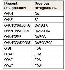
Table 1: Cooling class designations
Loading transformers beyond nameplate rating
There are different reasons why transformers become overloaded or why utilities may choose to overload them beyond their nameplate ratings. One reason is because the load demand has caught up or surpassed the transformer capacity and additional capacity is needed. Due to the complexity and exposure of the power system, no matter how well it is designed, failures are going to occur. It is the primary function of protective equipment to recognise such faults and isolate the faulted element from the rest of the system. This will cause the power flow to find new ways to reach the load demand. Transformers that find themselves on such paths might experience overloads beyond their normal capacity. It is possible to intelligently overload transformers to a rating that is still safe to operate by using the IEEE guide for loading of mineral-oil transformers IEEE C57.91. The guide outlines the risks, theory and calculations that make it possible to overload transformers. Understanding the aging of the insulation and how to calculate the hottest-spot winding temperature are of vital importance in order to know how much a transformer can be safely overloaded.
Thermal model for transformer
When a transformer is energized and loaded at ambient temperature (θa), dissipation caused by core losses, winding losses, stray losses in the tank and metal support structures are sources of heat which cause the transformer oil and winding temperature rise. The transformer oil is cooled by the radiator assembly and flows to the bottom of the cooling ducts to reach bottom oil temperature (θbottom). The transformer oil flows vertically upward the winding ducts and exits the winding ducts at the top winding duct oil temperature. The transformer oil enters the radiators at the top oil temperature in the main tank (θtop). IEEE Loading Guide has been used to calculate hotspot temperature. The bottom and top oil temperature are measured during temperature rise test in manufacturer’s plant. In the same process the average oil temperature rise is calculated, and the average winding temperature is obtained by resistance variation. These thermal parameters are used to construct the thermal model of oil-immersed transformer, as shown in Figure.1. In this model, the hot-spot temperature is the sum of ambient temperature, top oil temperature rise (Gθtop), and hot-spot to top oil temperature gradient (GθH= H.g), where H is hot-spot factor and ‘g’ is thermal gradient between winding and oil average temperatures.
This diagram is based on the following assumptions:
- The change in the oil temperature inside and along the winding is linearly increasing from bottom to top.
• The increase in the winding temperature from bottom to top is linear with a constant temperature difference ‘g’.
![]()
Fig. 1: Thermal model of oil-immersed transformer…
At the top of the winding HST is higher than the average temperature rise of the winding. The difference in the temperature between the hot spot and the oil at the top of the winding is defined as H.g, where H is a hot spot factor. It may be vary from 1.1 to 1.5, depending on short circuit impedance, winding design and transformer size.
![]()
How does temperature affect the life of a transformer?
Temperature is one of the prime factors that affect a transformer’s life. In fact, increased temperature is the major cause of reduced transformer life.
Further, the cause of most transformer failures is a breakdown of the insulation system, so anything that adversely affects the insulating properties inside the transformer reduces transformer life.
Such things as overloading the transformer, moisture in the transformer, poor quality oil or insulating paper, and extreme temperatures affect the insulating properties of the transformer.
Most transformers are designed to operate for a minimum of 20-30 years at the nameplate load, if properly sized, installed and maintained. Transformers loaded above the nameplate rating over an extended period of time may have reduced life expectancy.
Transformers with lower temperature rise often use windings with lower resistance. The low resistance per unit length of copper allows lower temperature rise transformers to be built without unnecessarily building a bigger transformer. For example, an aluminium-wound transformer coil requires conductors with approximately 66% more cross-sectional area than a copper-wound transformer coil to obtain the same current carrying capacity.
IEEE standards and temperatures
It is clear that the temperature produced by the transformer losses can affect the life span of the insulation.
To ensure the longevity of the transformer, transformer manufactures must guarantee that their designs are capable of operating within specified standards.
But what are the guaranteed temperatures limits stated by the standards?
The operating limits are bounded by the ambient temperature, the average winding temperature, and the maximum winding hottest-spot temperature.
According to the IEEE C57. 12.00 standard, power transformers are rated on a maximum ambient temperature of 40°C, and the average ambient temperature shall not exceed 30°C in a 24-hour period.
This standard also states that an average winding rise of 65°C shall not be exceeded when the transformer is operated at its rated load (kVA), voltage (V), and frequency (Hz).
In other words, based on the ambient temperature criteria, the average temperature of the winding cannot exceed 65°C above ambient, when operated at rated conditions.
Maximum hottest-spot winding temperature cannot exceed a value of 80°C above ambient. The IEEE C57.91states that under a continuous ambient temperature of 30°C, the maximum hottest-spot winding temperature should not exceed110°C.
Test methods for temperature-rise determination
It may be agreed, in special cases, to perform a test with approximately rated voltage and current by connection to a suitable load. This is mainly applicable to transformers with low rated power.
Test to steady state by short-circuit method
During this test the transformer is not subjected to rated voltage and rated current simultaneously, but to the calculated total losses, previously obtained by two separate determinations of losses, namely load loss at reference temperature, and no-load loss .The test set up is shown in figure 2.
The purpose of the test is two fold,
- To establish the top oil temperature-rise in Steady-state condition with dissipation of total losses.
2. To establish the average winding temperature rise at rated current and with the top oil temperature rise as determined above.
This is achieved in two steps:
Total loss injection
First the top oil and average oil temperature-rises are established when the transformer is subjected to a test voltage such that the measured active power is equal to the total losses of the transformer.
The test current will be above rated current to the extent necessary for producing an additional amount of loss equal to the no-load loss, and the winding temperature rise will be correspondingly elevated.
The oil temperature and cooling medium temperature are monitored, and the test is continued until a steady-state oil temperature rise is established.
The test may be terminated when the rate of change of top oil temperature-rise has fallen below 1 k/h and has remained there for aperiod of 3 h.
Rated current injection
When the top oil temperature rise has been established, the test shall immediately continue with the test current reduced to rated current for the winding combination connected.
This condition is maintained for 1h, with continuous observation of oil and cooling medium temperatures.
At the end of the 1h, the resistances of the windings are measured, after a rapid disconnection of the supply and short circuits.

Fig.2: General Test set up for Temperature rise test…
The values of average temperature of the two windings are determined from the resistances. During the period with rated current the oil temperature falls. The measured values of winding temperature shall therefore be raised by the same amount as the average oil temperature-rise has fallen from the correct value.The corrected winding temperature value minus the cooling medium temperature at the end of the total losses injection period is the winding average temperature-rise.
The average winding temperature shall be determined using the value of resistance at the instant of shutdown. In this case, when making power shutdown, connecting the DC power supply and measuring the winding resistance, the winding temperature goes down, resulting in the lower measurement of the winding resistance compared to the instant of power shutdown. The fall of the resistance from power shutdown to measuring winding resistance is calculated by the extrapolation as indicated below in figure 3.

Fig. 3: Extrapolation method to predict winding rise…
It has been proved experimentally that extra cooling provided by addition of radiators for a 250 kVA, 11/.433 kV drastically reduces the winding temperature rises up to 8 deg.C on both LV and HV windings during temperature rise test. Test results can be seen by comparison given in graph 1.

Graph1: Control of temperature rise by radiator fins…
Determining winding hot spot
The hottest-spot winding temperature is the principal factor in determining life due to loading. The temperature cannot be measured directly because of the hazards in placing a temperature detector at the proper location because of voltage. Standard allowances have, therefore, been obtained from tests made in the laboratory and the insertion of thermocouples is represented in figure.4.

Fig. 4: Location of sensors to predict hot spot temperature…
The hottest-spot copper temperature is the sum of the temperature of the cooling medium, the average temperature rise of the copper, and the hottest-spot allowance. The hottest-spot allowance at rated load is 10°C for transformers with 55°C average winding temperature rise by resistance and 15°C for transformers with 65 °C average winding temperature rise by resistance.
The Hot Spot Temperature (HST) value depends on the ambient temperature, the rise in the Top Oil Temperature (TOT) over the ambient temperature, and the rise in the winding HST over the top oil temperature.
Therefore, the Hot Spot Factor (H) in IEC 60076-2 appeared to be 2.0. In order to estimate the transformer life accurately, the hot spot temperature or hot spot factor detected by the paper winding should be applied to the IEEE and IEC standards. The thermal imaging of transformer during temperature rise gives index for heat distribution as shown in the figure 5. The losses gradually increase the temperature, damaging the insulation and overheating the core hence causing the failure.
The following are the common reasons of transformer failures due to losses.
High ambient temperature
External ambient will influence the result of the temperature rise test.The ambient temperature of the installation site should always be specified when ordering a transformer.
The failure could result in the overheating of the transformer coils leading to deterioration in the coil insulation and resulting in a complete failure of the transformer coil.
![]()
Fig. 5: Thermal imaging of transformer under TR test…
Inadequate airflow & cooling
Transformers will dissipate two types of losses, No load losses, which are iron (Fe) losses and Fullload losses which are Copper (Cu) and iron losses combined, in larger transformers these can be substantial, it is therefore essential that adequate space around the transformer or enclosure is left, to allow a natural free flow of air.
Sufficient ventilation should also be supplied to allow for a constant change of air in and around the transformer/enclosure. Failure to do so can result in the ambient air temperature dramatically increasing and consequent result in transformer failure.
Overloading
Transformers are designed to work at a given load to exceed that rating and due to harmonic loads will result in an increase in temperature. This increase in temperature will cause a rapid deterioration in the coil insulation and cause a complete failure of the transformer coil.
Cooling
The winding copper maintains its mechanical strength up to a few hundred degrees Celsius. The transformer oil does not degrade considerably below around 140°C however paper insulation deteriorates greatly if its temperature rises above about 90°C. The cooling oil flow must, consequently, guarantee that the insulation temperature is kept below this temperature as much as possible. It is by all means possible, often times with little effort, to lower the average temperature through a well-targeted intervention into the cooling system control. In extreme cases, i.e., at high ambient temperatures and questionable design of the internal cooling system, it might even be sensible to change over to a water cooling system, if it promises to lower the overall system temperature by 10-15K. The cooling methods can be either internal or external, which includes oil natural, oil forced, air natural and air forced.
The oil is moved by the thermosiphon effect through the windings. A suitable temperature difference must be achieved between the upper and the lower part. The difference is often about 15-25K by internal cooling methods. The temperature difference is mostly about 10 K by external cooling.
Conclusions
In this article, a review was made by analysing and discussing the existing studies with effect of temperature rise and factors influencing on oil-transformer aging. A condition monitoring system is considered to be essential to ensure reliability and sustainability of the transformer. At the same time, the manufacturers have to make progress in controlling the generation and the dissipation of the losses as well as using traditional or higher-temperature materials. Thus, they have to develop new calculation tools based either on simple analytical methods or using thermal modelling.Today with modern cooling systems, the effect of solar heat flux can be reduced, but the temperature is a limiting factor that should not exceed from a predetermined value.
Since, in most apparatus, the temperature distribution is not uniform, that part which is operating at the highest temperature will ordinarily undergo the greatest deterioration. Therefore, in aging studies, it is usual to consider the aging effects produced by the hottest spot temperature important.The aging pattern of the distribution transformer under extreme conditions is under further study.

If you want to share any thought or feedback on this article then please leave a comment below.


