

Ascending changes in the way we generate, transmit and use of electricity in developed economy or highly industrialised society, prioritised the maintenance of continuity of supply to consumers. With the goal to be integrated in smart cities, the safety of electrical equipment by fast disconnection of the power supply in case of fault events like leakage current, electrical arc, over current or overvoltage is taken care through switchgear such as disconnecting switches, circuit breakers, etc. For the systems up to 33kV, the more costly circuit breakers are getting replaced with load break switches. A load break switch is a type of switching device used for voltages in the range of 12 to 36 kV and must have the following capabilities:
-Interruption of current equal to its continuous current rating at the system voltage and the power factor of the normal load
-Designed to possess enough insulation to isolate the circuit in closed position.
-Interrupting small capacitive and inductive currents which is essential for disconnecting the unloaded overhead lines, transformers, cables, etc.
-Carrying the maximum fault current for the duration required by the interrupting device to clear the fault.
-Making on the terminal fault at rated voltage.
The basic functional difference between Load break switch and circuit breaker is that the former cannot interrupt the short circuit currents. The following figure 1 shows the how the load break switches are employed in a substation.

substation
Load Break Switch
The AC high voltage load break switch is used in indoor or outdoor medium voltage systems at rated frequency 50/60 Hz. The load break switch is generally composed of disconnect blade, arc extinguishing chamber and operating mechanism. The arc extinguishing chamber will be made of insulating material with merits of high dielectric performance, and arc-endurances.
Generally, two types of load break switches (LBS) have been developed namely air-blast and SF6.In air-blast type, the interrupter heads same as those of used for isolation purpose in air-blast circuit breakers are employed for making and breaking currents. In SF6 type LBS, the gas serves as insulating and arc quenching medium.
The three-phase load break switch is installed on one sectional galvanized steel base, joint together with one drive axis to ensure closing and opening of three poles synchronously. The switch opens or closes under rated load current, without requiring any secondary protection device.
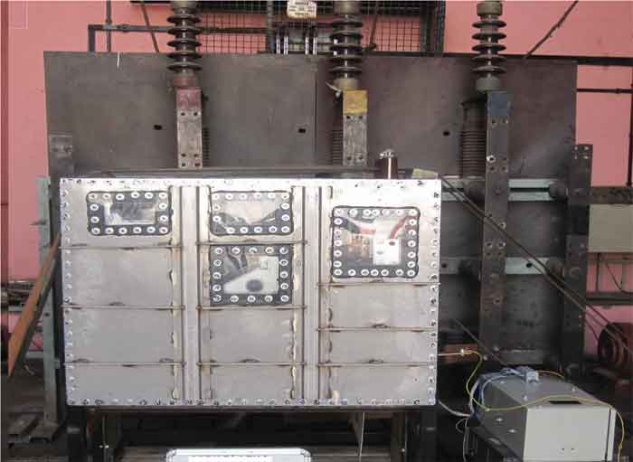
Load break switch switches the current by mechanically moving their contacts with an appropriate speed in order to make (close) or break (open) the current. It is exposed to mechanical, thermal and dielectric stresses during switching operation. Hence, for investigating and in detail exploring the interrupting capabilities of load break switch, they need to undergo various test duties according to IEC 62271-103. The essential parameters that are taken into consideration for analysing the behaviour of the load break switch during breaking tests are the current levels and the transient recovery voltage (TRV). The following figure 2 shows the load break switch tested at CPRI, Bhopal.
Role of CPRI
CPRI is a pioneer testing organisation in India with six decades expertise in the short circuit and dielectric testing, short circuit design data reviews, quality control checks and stage inspection of various power system equipment. CPRI is continuously engaged in testing of various types of switchgear equipment from last six decades and issuing test certificates and test reports as per national and international standards.
To prove the satisfactory performance of the load break switch, various test duties have been carried out as specified in the international standards. Several load break switches of rated voltage upto 12kV, and of current rating 200A, 400A, 630A, etc of various manufacturers have been tested at CPRI, Bhopal.
Test Duties
The following table 1 indicates the various test duties that a load break switch has to be undergone according to IEC 62271-103 to verify the breaking and making capabilities.


Make-break operating cycles shall be carried out for test duties TDload, TDloop, TDcc, TDlc, TDef1 and TDef2. The opening operation shall follow the closing operation with a time delay between the two operations at least sufficient for any transient currents to subside.
Mainly active load circuit (test duty TDload)
The rated mainly active load-breaking current is the maximum mainly active load current that the switch shall be capable of breaking at its rated voltage. The current to be interrupted shall be symmetrical, but at the instant of interruption the value of the dc-component of the breaking current is considered negligible as it is equal to or less than 20 per cent as stated in table 2. When Iload flows through load break switch, the current carrying parts of the device will be subjected to thermal and mechanical stresses. When this current is interrupted by the switch, fast rising voltage appears across its contacts called as transient recovery voltage. This test duty is conducted so as to analyse the load-breaking capability of the switch and withstand capability of the peak of transient recovery voltage after the current interruption. The circuit needed for this test duty on load break switch is shown in figure 3.

The parameters and their tolerances that are used for conducting this test duty are listed out in table 1 and 2. The following figure 4 indicates a recording of break-make operation on 12kV,630A Load break switch during mainly active load current test duty TDload2.

Closed loop switching tests
Closed loop breaking capacity is breaking capacity when opening a closed-loop distribution line circuit, or a power transformer in parallel with one or more power transformers (as shown in line diagram of figure 1), i.e., a circuit in which both sides of the switch remain energised after breaking. So, to analyse this breaking capability, TDloop test duty is conducted on the Load break switch with the parameters and tolerances as listed in table 1 and 2.
Capacitive current switching tests
When an unloaded transmission line, cables, etc are suddenly opened, interruption of capacitive currents causes excessive voltage surges which will stress the insulation medium of the switching device. So, when load break switch interrupts line charging capacitive current, to analyse its interrupting capability line charging current test duty (TDlc) and to analyse breaking of cable charging current capability, cable charging current test duties (TDcc1 and TDcc2) is conducted. The parameters and their tolerances that are used for this conducting this test, are listed out in table 1 and 2.
Short-circuit making tests
The load break switch sometimes, closes on to an existing fault. In such cases, maximum peak of first major current loop of the current in a pole of a switch during the transient period following the initiation of current during a making operation will be observed. The load break switch must be able to close without hesitation as contacts touch and must be able to withstand the high mechanical forces during such closure.
Short-circuit making tests shall be performed on a switch which has been subjected to at least 10 make-break operating cycles at 100 per cent mainly active load as required for test duty TDload.
For class E1 switches, the tests shall be performed with a sequence of two C operations with a no-load O in between, i.e. C – O (no-load) – C.
For class E2 switches, the test sequence is 2C – x – 1C.
For class E3 switches, the test sequence is 2C – x – 1C – y – 2C, where x represents arbitrary switching tests, or even no-load tests.
The switch shall be able to make the current with pre-arcing occurring at any point on the voltage wave. Two extreme cases are specified as follows:
-Making at the peak of the voltage wave, leading to a symmetrical short-circuit current and the longest pre-arcing time;
-Closing at the zero of the voltage wave, without pre-arcing, leading to a fully asymmetrical short-circuit current. During the short-circuit making tests series, both requirements a) and b) shall be met once for class E1 switches, once for class E2 switches and twice for class E3 switches.
The circuit needed for this test duty on load break switch is shown in figure 5. The parameters and their tolerances that are used for this conducting this test, are listed out in table 1 and 2.

The following figure 6 indicates a recording of make operation on 12kV, 630A Load break switch during short circuit making test duty for a making current of 25kA.

switch during short circuit making capacity test duty.
Behaviour of switch during breaking tests
-The switch shall perform successfully without evidence of mechanical or electrical distress.
-There shall be no flame or material ejected from the switch, that may be harmful to operating personnel.
-For capacitive current breaking tests, re-strikes are permitted during switching for class C1 switches.
-For class C2, if one single re-strike occurs along an entire specific series of capacitive switching, for example test duties TDcc1 and TDcc2 for cable charging current, the number of operations as indicated shall be doubled for this test series. The additional operations shall be performed on the same switch and without any maintenance or reconditioning in between. The requirements for class C2 are still fulfilled, if no further re-strike occurs. A re-ignition followed by interruption at a later current zero shall be treated as a breaking operation with long arcing time.
-There shall be no significant leakage current to the earthed structure or screens, such as to endanger an operator or damage insulation materials.
-There shall be no outward emission of flame or metallic particles from the switch during operation such as might impair the insulation level of the switch.
-NSDD (Non-sustained disruptive discharge) may occur during the recovery voltage period following a breaking operation. However, their occurrence is not a sign of distress of the switching device under test. Therefore, their number is of no significance to interpreting the performance of the switch under test.
Condition of switch after breaking tests and short-circuit making tests
-After performing the specified breaking tests on one sample and after test duty TDma, the mechanical function and the insulators of the switch shall be in practically the same condition as before the tests.
-The requirement of being capable of carrying its rated normal current is considered met if one of the following criteria is satisfied:
-Visual inspection of the main contacts shows evidence of their good condition; or if impracticable or unsatisfying,
-The resistance measured, as close as possible to the main contacts, does not exhibit an increase of more than 20 per cent compared with resistance measured before the test. Before measurement of contact resistance, a maximum of 10 no-load operations may be done, or if the condition of b) is not satisfied
-A test under rated thermal maximum current demonstrates that no thermal runaway occurs, by monitoring the temperature at the points where resistance measurement were made until stabilization, and that the limits of temperature and temperature rise are not exceeded. During this test, no other temperature measurement is made inside of the switching device. If the stabilisation cannot be obtained, or the temperature and temperature rise are exceeding the limits, then the condition check has failed and the switch is considered to have failed the test duty as well.
Conclusion
In the testing laboratory, the source has to supply high fault current and fast rising TRVs to evaluate the load break switch performance. The guidelines for setting the fault current magnitude and Transient Recovery Voltage parameters are given in IEC standard 62271-103. These parameters represent the most onerous system conditions.
The medium voltage switchgear manufacturers in and around central part of our country and other places utilise CPRI, Bhopal laboratory for circuit breaker certification and development. This facility is a boon for developing not only load break switch and other switchgear equipment like fuses, disconnectors, earth switches, circuit breakers and lightning arresters etc.

Yugal Agrawal
Joint Director STDS, Central Power Research
Institute, Bhopal

K.Sharath kumar
Engineering Officer Gr-II,
STDS, Central Power Research Institute,
Bhopal


