

According to NFPA 70E, every year more than 2000 workers are hospitalized in extensive injured condition caused by arc flash accidents. Therefore, to recognize and understand Arc flash phenomena and its significant threats, IEEE and NFPA are applying efforts to support research and development.
Arc Flash Phenomena
Arc flash, a type of electrical explosion, is one of the most complex e-Hazard in the workplace. Day by day in the electrical safety world its understanding is gaining significant importance. The basic phenomena of the arc flashes, arc blast, electric arc, electrical explosion are the same. Basically, arc is a flow of electricity through ionized gases. When an arc flash occurs, large amount of energy dissipates from conductive plasma. Superheated ambient air produces a rapid volumetric expansion known as arc blast and consequently an explosion. An arcing fault usually occurs between phase bus bars or from phase to neutral or ground. During this event, intense light with sound waves, shrapnel, molten metal with toxic gases and smoke are generated which become components of the arc flash as shown in Figure 1. Due to the aforesaid hazard, a person exposed to arc flash may suffer severe burns, lung damage, vision loss, eardrum ruptures and even death.

Some Important Arc Flash Terminology
Some important terminologies used for arc flash analysis and mitigation through IEEE Std. 1584 & NFPA 70E are given below.
Fault Current
– Arcing fault current: Fault current flows through an electrical arc plasma.
– Bolted fault current: Short circuit current flows between conductors at different potentials having zero or negligible impedance.
– Fault current: A current that flows from one conductor to another conductor or one conductor to ground due to an abnormality produced in the system.
– Available fault current: It is the fault current that can be provided by the serving grid or utility, owned generators and large electric motors, subjected to the impedance of the path.
Hazards
– Shock hazard: A dangerous condition associated with the release of energy.
– Electrical hazard: A dangerous condition as a consequence of shock, arc-flash bum, thermal bum, or blast due to unintentional contact or failure of equipment.
– Electrical shock: Physical stimulation that occurs when electrical current passes through the body.
– Arc-flash hazard: A dangerous condition occurred due to electric arc produced by release of energy.
– Flash hazard analysis: A method to determine the risk of personal injury as a result of exposure to incident energy from an electrical arc flash.
Grounding
The solidly grounded electrode is treated as a grounded system while open or high or low resistance grounding is treated as an ungrounded system.
Total Clearing Time
It is the sum of relay operating time and breaker interrupting time.
Incident Energy
It is the amount of energy incident on the surface at distance of Arc Flash Boundary (AFB).
The Incident Energy of 1.2 Cal/ cm2 for bare skin is used in solving the equation for arc flash boundary in IEEE 1584 Guide for performing Arc Flash Hazard Calculations.
Incident Energy and Clearing Time vary proportionately. Since in the steep portion of protective device time-current curves, a small change in current causes a big change in operating time. Therefore, variation in arc current may have a big impact on incident energy.

Arc Flash Boundary & Limits of Approach
Arc Flash Protection Boundaries are described in the table 2. Arc Flash Protection Boundaries depicted in the figure 2.


Arc flash limits of approach are depicted in the figure 3. Arc Flash Boundaries and Approach Limits as per NFPA 70E-2015 standards are depicted in figure 4.


Equipment Classes, Typical Bus gap, and Working distance
The typical values used for Arc Flash analysis, as Equipment classes, Bus gaps, Distance x factor and Working distance with isolated main PD are tabulated.
Typical working distance: It is the sum of the distance between the worker standing in front of the equipment, and from of the front of the equipment to the potential arc source inside the equipment. Thus, it is the space between the possible arc point and head and body of the operator.
Hazard Category/ Level, Incident Energy and Recommended PPE
Considering the magnitude of the arc energy within the AFB, all parts of the body which may be exposed to the Arc Flash need to be covered by Arc Rated (AR) clothing, helmet or headgear, face shield, safety glasses, gloves, shoes etc. The protective clothing should limit the incident energy reaching the chest or face of the person equal to or less than 1.2 Cal/cm2. AR clothing provides thermal insulation and is also self-extinguishing. NFPA’s minimum recommended a rating of PPE in Cal/ cm2 at a working distance from the arc source is depicted in Table 3.

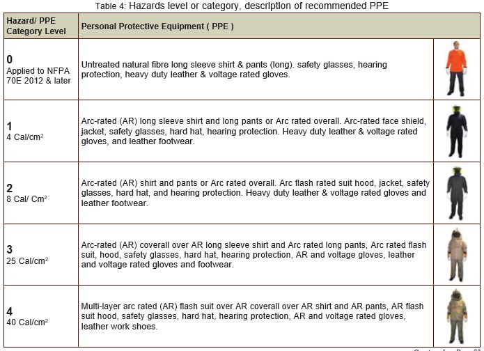
As per hazards level or category, description of recommended PPE is tabulated in the Table 4.

Arc Flash Analysis: NFPA 70E Tables versus IEEE Std.1584
NFPA 70E Tables highlight specific PPE to be used on various electrical equipment. These tables are based on fundamental assumptions about the available fault current and the overcurrent device clearing time.
In order to provide appropriate protection to the technician, the necessary calculations must be performed to find the short circuit currents and the Over Current Protection Device (OCPD) opening times. For effective use of the tables, it must be verified that the available fault current and the OCPD tripping time are both equal to or lower than the values assumed for developing the tables. IEEE Std.1584-2002 directs analysis procedure with design and real-time configuration data of the network. Perform coordination for all protective devices and find Bolted and Arc fault current. Find incident energy and arc flash boundary for selected working distance and select the appropriate PPE.
Analysis Procedure as per IEEE Std. 1584-2002 is given below.
– Collect the design data of the system and installation from their data sheet.
– Determine the system modes of operation
– Determine the bolted fault currents
– Determine the arc fault currents
– Find the protective device characteristics and the duration of the arcs
– Document the system voltages and classes of equipment
– Select the working distances
– Determine the incident energy for all equipment
– Determine the flash-protection boundary for all equipment
– Select appropriate PPE.
Arc Flash protection – The Best Practices
Preventive maintenance
The best practices of preventive maintenance help to reduce arc flash exposure like:
– Prevent entrance of rodents and birds in the panels.
– Check for loose connections,
– Thermography for overheated terminals
– Prevent deposition of excessive moisture
– Ensure proper operation of relays, breakers, and contactors
– Clear the fault before placing a new fuse
– Off-line work is always preferable. If it is unavoidable, use insulated tools with torque controller
– Avoid use of cleaning chemicals, spray, painting etc. on live parts.
Protection schemes
– Protection device coordination study
It should be performed in order to select proper settings of the overcurrent protective devices which help to reduce the bolted fault and arcing fault current.
– Temporarily settings of protection device
During system maintenance settings of protective devices should be reduced. It will help to mitigate incident energy exposure.
– Fault level reduction
If system load flow permits, thus, during the maintenance incident energy can be reduced by means of a change of operating configuration of the network by:
i. Opening of tie circuit breaker
ii. Isolation of sources
iii. Selection of low fault level sources
In the following network, power is supplied by grid and generator. Thus, incident energy at PMCC cable bus for different configurations of the system are simulated as shown in Figure 5.
Results of simulation are summarised in the Table 5.


– Current Limiting Fuse & Reactor
Fault current, as well as arcing current, can also be reduced by use of current limiting fuse and reactors. This limits the incident energy exposure.
– Arcing Time reduction
Incident energy or Arcing Current Time can be reduced by reducing arcing time. Arcing time can be reduced by reducing,
– Safety margin for relay and breaker operation,
– Combination of bus differential protection with instantaneous operation,
– Retrofitting of timeovercurrent relays with the delayed instantaneous trip.
– Remote operation such as racking and switching
Racking and switching from remote do not reduce arcing fault energy but keep the operator outside the arc flash boundaries.
– Arc-resistant switchgear
This type of switchgear has the capability to confine the incident energy of the arc flash
and vent off the energy out of the switchgear in a direction away from the operator.
– Optical sensor technology
This technology detects the light from the arc flash and initiates a shutdown. A combined detection of light and current allows clearing times of the order of 1/4 cycle or even lower.
– Arc flash current path alternation method
This method provides with proper arc detection system. As the arc is initiated, an alternate lower impedance current path than the fault path in order to and capture and fast transfer the arcing fault.
Arc flash hazard is a real threat to equipment, operator, and operations. For protection, PPE is to be used but higher category PPE may be uncomfortable in regular operation causes a further degree of risk increases. Since every industry has a different type of process with a different type of operations, therefore, risk management process is also different for different types of processes. For every process, identification of risk and protection is essential, therefore, to ensure safety and regulatory compliance, operators must develop and implement feasible solutions for mitigation of workplace hazards.


